BA_PH_546-100_EN_06-22.docx
49
15.2
Replace / Tighten the V-Belts
1.
Switch off the main switch (
35
) and lock it.
2.
Remove the rear cover next to the control cabinet door.
3.
Move the planing fence completely to the front
4.
To retighten
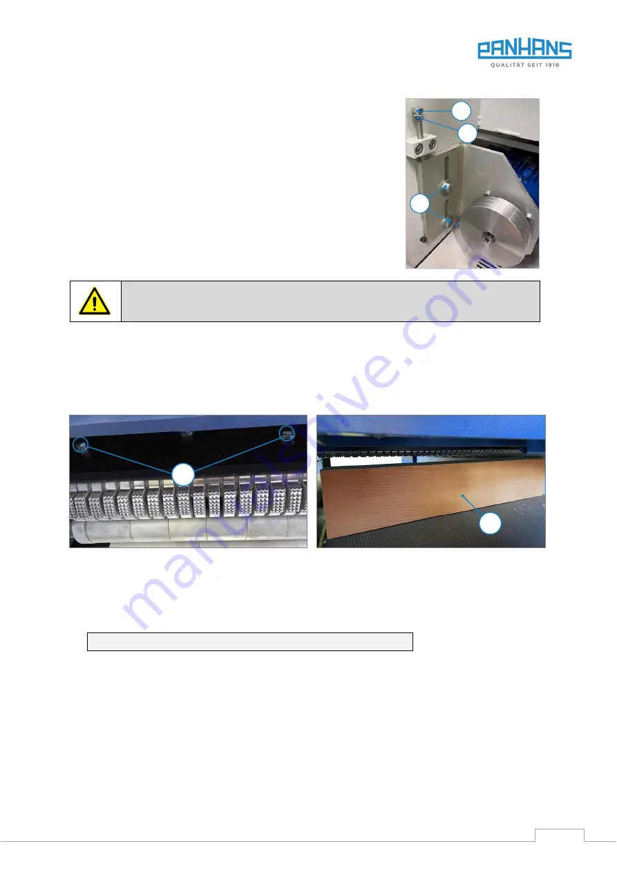
, loosen the two screws (
S
) and the lock nut (
K
) and tighten
the motor block via the adjusting screw (
V
) by turning it clockwise
↻
.
Important:
Do not tighten the V-belts too much. It is correctly ten-
sioned when it can be pressed through between the V-belt pulleys by
about 1 cm with a lateral force of approx. 2 kg.
5.
Remount the rear cover.
6.
To replace the V-belts
, loosen (
S
), (
K
), and (
V
) so that the motor can be
lifted sufficiently to remove and re-install the belts
7.
For tightening
proceed as described in steps 4. to 5.
Figure 61: V-belt pulleys
Switch off the machine during maintenance and repair work and secure it against being
switched on again unexpectedly! Lock the main switch with a padlock!
15.3
Retighten the Feed Chain
The feed chain is equipped with an automatic chain tightener that always ensures the correct tension. Manual
retensioning is therefore not necessary. The chain only needs to be replaced when it is excessively worn.
15.4
Adjusting the Fingers of the Anti-Kickback Device
Figure 62: Two of the four adjustment screws
•
Loosen all four M6 adjusting screws (
E
) in the slot-
ted holes with an open-end spanner SW10, push
them all the way up and lightly tack them in place.
Figure 63: Squared timber as adjustment aid
•
Prepare a dressed squared timber (
K
) with a
length of approx. 620 mm and a height of at least
150 mm. This serves as an adjustment aid.
•
Measure the actual height of the squared timber and set 2 mm more on the thicknesser.
Example:
Height squared timber = 200 mm | Setting thicknesser = 202 mm
•
Loosen the tacked adjusting screws (
E
) and make sure that all fingers are resting on the squared timber.
•
Now press the four adjusting screws (
E
) all the way down and tighten them again.
•
The process is completed.
S
K
V
E
K


