background image

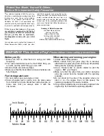
Inspect your radio installation and confirm that all
the control surfaces respond correctly to the
transmitter inputs. The engine operation must also
be checked by confirming that the engine idles
reliably, transitions smoothly and rapidly to full
power and maintains full power, indefinitely. The
engine must be “broken-in” on the ground by running
it for at least two tanks of fuel. Follow the engine
manufacturer’s recommendations for break-in.
Make sure that all screws remain tight, that the
hinges are secure and that the prop is on tight.

Whenever you go to the flying field, check the
operational range of the radio before the first flight
of the day. First, make sure no one else is on your
frequency (channel). With your transmitter on, you
should be able to walk at least 100 feet away from
the model and still have control. While you work the
controls, have a helper stand by your model and
tell you what the control surfaces are doing.
Repeat this test with the engine running at various
speeds with a helper holding the model. If the
control surfaces are not always responding
correctly, do not fly! Find and correct the problem
first. Look for loose servo connections or corrosion,
loose bolts that may cause vibration, a defective
on/off switch, low battery voltage or a defective
receiver battery, a damaged receiver antenna, or a
receiver crystal that may have been damaged from
a previous crash.

Note: Failure to follow these safety precautions
may result in severe injury to yourself and others.

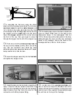
Keep all engine fuel in a safe place, away from high
heat, sparks or flames, as fuel is very flammable.
Do not smoke near the engine or fuel; and
remember that the engine exhaust gives off a great
deal of deadly carbon monoxide. Do not run the
engine in a closed room or garage.

Get help from an experienced pilot when learning
to operate engines.

Use safety glasses when starting or running
engines. Do not run the engine in an area of loose
gravel or sand; the propeller may throw such
material in your face or eyes.

Keep your face and body as well as all spectators
away from the plane of rotation of the propeller as
you start and run the engine.

Keep these items away from the prop: loose
clothing, shirt sleeves, ties, scarfs, long hair or
loose objects such as pencils or screwdrivers that
may fall out of shirt or jacket pockets into the prop.

Use a “chicken stick” or electric starter to start the
engine. Do not use your fingers to flip the propeller.
Make certain the glow plug clip or connector is
secure so that it will not pop off or otherwise get
into the running propeller.

Make all engine adjustments from behind the
rotating propeller.

The engine gets hot! Do not touch it during or right
after operation. Make sure fuel lines are in good
condition so fuel will not leak onto a hot engine,
causing a fire.

To stop a glow engine, cut off the fuel supply by closing
off the fuel line or following the engine manufacturer’s
recommendations. Do not use hands, fingers or any
other body part to try to stop the engine. Do not throw
anything into the propeller of a running engine.

Read and abide by the following Academy of
Model Aeronautics Official Safety Code:

General
1. I will not fly my model aircraft in sanctioned
events, air shows, or model flying demonstrations
until it has been proven to be airworthy by having
been previously successfully flight tested.

2. I will not fly my model aircraft higher than
approximately 400 feet within 3 miles of an airport
without notifying the airport operator. I will give
right of way to and avoid flying in the proximity of
full-scale aircraft. Where necessary an observer

AMA Safety Code (excerpt)

Engine Safety Precautions

Range Check Your Radio

Ground Check the Model

19

Содержание Hobbistar 60 MKII

Страница 1: ...as quickly as possible 1 ALWAYS return your entire system including airplane and radio 2 Disconnect the receiver battery switch harness and make sure that the transmitter is turned off Disconnect all...

Страница 2: ...ow to Purchase Missing pieces Contact Hobby Services see warranty front page Plans Construction Plans Plans are not available for ARF models Manual Instructions Contact Hobby Services see warranty fro...

Страница 3: ...ng Joiner 12 Aileron Servo Tray 13 Plywood Servo Tray 14 Engine Mount Straps 15 Aileron Servo Tray Blocks 16 Wing Joining Tape 17 Pushrods and Pushrod Tubes 14 17 Clothespins Epoxy Brushes GPMR8062 Mi...

Страница 4: ...the location of the throttle servo and throttle pushrod exit on the firewall so plan ahead Radio Equipment In selecting a radio system for your Hobbistar 60 MKII you ll need at least a 4 channel radi...

Страница 5: ...ns Before you fly 1 Make sure that no other fliers are using your radio frequency 2 Your radio transmitter must be the FIRST thing you turn ON and the LAST thing you turn OFF 3 Double check all contro...

Страница 6: ...eral amount of 30 minute epoxy to the joiner and the wing ribs Put the wing joiner into the joiner box in the wing and push the two wing halves together and allow the glue to cure 4 Use masking tape t...

Страница 7: ...to accommodate most servos If it is not deep enough for your particular brand of servos glue the servo tray to the two 1 4 6mm balsa blocks included in the kit and then glue the blocks to the wing wi...

Страница 8: ...the fuselage Do not glue it in place 6 Apply a piece of masking tape across the top of the fuselage at the back of the wing saddle Mark the center of the fuselage on the tape Insert a T pin on the cen...

Страница 9: ...r in relation to the wing The distance from the top of the stab to the bottom of the wing should be the same If each end of the stabilizer is not equal in distance from the wing lightly sand one side...

Страница 10: ...selage bottom The hole needs to be drilled at a 30 angle Cut one of the white tubes to 11 and rough it up with 240 grit sandpaper Insert the tube into the fuselage so that the end of the tube is even...

Страница 11: ...m screws All three wheels should turn freely If not trim the inside of the wheel slightly 1 Locate the two metal engine mount straps 2 Put your engine onto the engine mount Note Depending on your engi...

Страница 12: ...ssembly into the fuel tank and tighten the stopper screw 7 Install the tank into the fuel tank compartment Apply a bead of silicone sealant around the fuel tank cap when installing the tank into the f...

Страница 13: ...here the holes need to be drilled Note When installing the control horns the centerline of the control horn holes must be the same as the center line of the hinge joint as shown in the above sketch Dr...

Страница 14: ...included with your radio system 5 Plug the switch into the receiver and the receiver battery Plug the servos into the receiver consult your radio instruction manual for proper installation if you are...

Страница 15: ...on the transmitter and receiver Set the throttle to full open Install the pushrod into the other screw lock pushrod connector then open the carburetor on your engine to full open Connect the throttle...

Страница 16: ...recommended by the engine manufacturer along with the spinner By moving the position of the clevis at the control horn toward the outermost hole you will decrease the amount of throw of the control su...

Страница 17: ...anced will be unstable and possibly unflyable 1 The balance point C G is located 3 1 2 89mm back from the leading edge of the wing Balance your Hobbistar 60 using a Great Planes C G Machine Airplane B...

Страница 18: ...ing servo horn screws clevises servo cords and extensions Follow the battery charging procedures in your radio instruction manual You should always charge your transmitter and receiver batteries the n...

Страница 19: ...ed room or garage Get help from an experienced pilot when learning to operate engines Use safety glasses when starting or running engines Do not run the engine in an area of loose gravel or sand the p...

Страница 20: ...vator stick on your radio Maintain a gentle climbing attitude until the plane is approximately 75 feet high then begin a turn away from the pit area Once airborne you will find that the plane is a ver...

Страница 21: ...model is statically trimmed It s only a starting point so don t be surprised if you wind up changing it all One other critical feature is that the ailerons must have their hinge gap sealed If shoving...

Страница 22: ...on problem while a loss of heading on the way back down is most likely a rudder situation Note that the Yaw test is the same looping sequences Here however we are altering rudder and ailerons instead...

Страница 23: ...de loops D Yaws right on insides and left on outside loops E Yaws left in insides and right on outside loops A Wings are level and plane falls to either side randomly B Falls off to left in loops Wors...

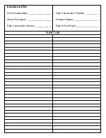
Страница 24: ...d Date __________________ Where Purchased ___________________ Date Construction Started _____________ Date Construction Finished __________ Finished Weight ____________________ Date of First Flight __...

Отзывы: