❏
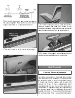
15. Cut off two leftover servo arms as shown in
the above diagram. These will be used to make a
simple strain relief for your receiver antenna.
❏
16. Drill a 1/16" [1.5mm] hole in the fuselage.
❏
17. After cutting the servo arms, thread the
antenna through the hole you drilled in the
fuselage and attach the antenna to the vertical fin
with a rubber band and T-pin as shown above.
❏
18. Install the propeller recommended by the
engine manufacturer along with the spinner.
By moving the position of the clevis at the control
horn toward the outermost hole, you will decrease
the amount of throw of the control surface. Moving
it toward the control surface will increase the
amount of throw. If these adjustments don’t
accomplish the job, you may need to work with a
combination of adjustments by also repositioning
the pushrod at the servo end. Moving the pushrod
towards the center of the servo horn will decrease
the control surface throw – outward will increase it.
Control Throw Adjustment
Final Assembly
16


