


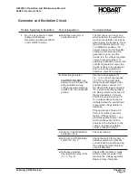


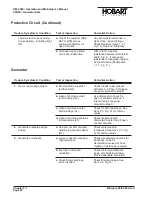


Generator and Excitation Circuit
Trouble, Symptom & Condition
Test or Inspection
Corrective Action
1.
No (or low) generator output
voltage in all phases.
Generator operating at 400 Hz
in AUTOMATIC mode.
a. Defective generator or
excitation circuit.
The first check is an easy one
which will allow the mechanic to
reach some definite conclusions
about where the trouble is. Place
the AUTO-MAN switch (33, Fig.
1) in MANUAL position. If a
normal voltage (for the rheostat
setting) is now produced, the
generator is good, and the
trouble is in the voltage regulator
circuit. Proceed to step C. If
switching to MANUAL control did
not affect generator output, the
trouble is likely in the generator,
but to prove the generator is
defective, proceed to step B.
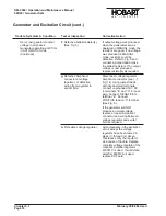
b. Defective generator.
CAUTION: DO NOT use
battery on unit to flash field
with generator turning
voltage regulator. Damage
results from the introduced
ground
Use the test receptacle (31,
Fig.. 1) to connect ungrounded
12-V DC to the exciter field.
Using leads with alligator clips
and test prods, connect 12-V
DC NEGATIVE lead to terminal
“D”. Terminal identifying letters
are plainly visible on the face of
the test receptacle. Connect
POSITIVE lead to terminal “F”.
If no output voltage change is
indicated when the exciter field
is energized, the generator is
defective.
Stop operations and see 2-3,
Para. 4 for further generator
testing. If the generator
produces approximately 140-V
AC when the exciter field is
energized, the trouble is in the
voltage regulator-excitation
circuit. Proceed to step C.
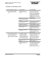
c. Defect in VOLTAGE REG.
excitation circuit.
Check as follows:
d. Defective AUTO-MANUAL
switch (33, Fig. 1)
Check the switch thoroughly. A
defective switch may prevent
current reaching and/or leaving
the voltage regulator. Replace
switch if defective.
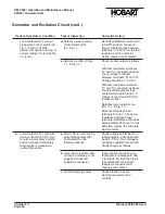
e. Defective excitation
deenergization relay (K16)
(1-1; 3, Fig. 8).
Check EDR contacts. A faulty
EDR can prevent power from
reaching the voltage regulator.
Replace relay if defective.
OM-2040 / Operation and Maintenance Manual
90D20 / Generator Sets
February 28/94 Revised
Chapter 3-1
Page 17
Содержание 6921 Series
Страница 2: ...This page intentionally left blank ...
Страница 223: ......
Страница 224: ......
Страница 225: ......
Страница 226: ......
Страница 227: ......
Страница 228: ......
Страница 229: ......
Страница 230: ......
Страница 231: ......
Страница 232: ......
Страница 233: ......
Страница 234: ......
Страница 235: ......
Страница 236: ......
Страница 237: ......
Страница 238: ......
Страница 239: ......
Страница 240: ......
Страница 241: ......
Страница 242: ......
Страница 243: ......
Страница 244: ......
Страница 245: ......
Страница 246: ......
Страница 247: ......
Страница 248: ......
Страница 249: ......
Страница 250: ......
Страница 251: ......
Страница 252: ......
Страница 253: ......
Страница 254: ......
Страница 255: ......
Страница 256: ......
Страница 257: ......
Страница 258: ......
Страница 259: ......
Страница 260: ......


