


Front view
Top view
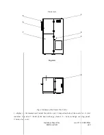
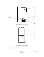
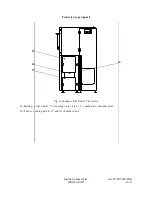
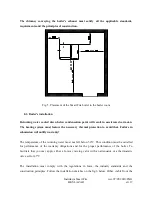
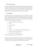
Fig. 2. Schema of the Smart Fire boiler
1 - display; 2 - thermostat reset (under the plastic cap); 2- inspection hole of the controller; 4 - fuel
container clap door 5 -knob of the heat exchange cleaner; 6 - heat exchange covering panel;
7- boiler door cover;
Instrukcja Smart Fire
wer. 07/05/2010/ENG
HKS LAZAR
str.9
2
4
5
3
6
7
1


