
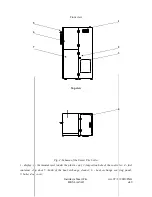
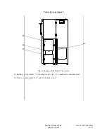


boiler body connects to the fuel supply system with the collar of the auger feeder.
Two covering panels are fixed in front of the boiler. You can access the combustion chamber and
the ash try chamber with the pair of inspection doors under the bottom panel. The upper panel
makes the upper part of boiler body. A control display showing current status of the boiler is fixed at
the front wall of the fuel container.
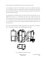
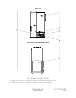
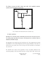
The inlet and outlet of the heating system water are located at the back wall of the boiler. These are
threaded pipe ends with a 1¼ " internal thread. The back wall also holds the exhaust collar
connecting the boiler to the flue system. The placement of the connectors has been detailed on the
fig.1. An outlet fan is fixed to the back wall next to the exhaust collar. Amount of air flown by the
fan is controlled by the system controller. A thermocouple monitoring exhaust temperature is fixed
in the exhaust collar.
The external covers and the body are insulated with mineral wool to reduce heat loss in operation.
The covers are made of steel sheets covered with high quality powder paint.
Fig. 1. Dimensions of the Smart Fire boiler
Instrukcja Smart Fire
wer. 07/05/2010/ENG
HKS LAZAR
str.8


