Manual
COHEDRA
®
& COHEDRA
®
Compact
1 Line Array Approaches
in Recent Years
Line arrays are a fixture on the contemporary sound
reinforcement scene. The design principle has its
origins in the stacks of cone loudspeakers that were
popular in the '70s.
Some 20 years later, the coherent wave front's ingress
into the high frequency range through waveguides
and acoustical mirrors ushered in a second genera-
tion of line arrays.
Here a line source makes use of the near field's dif-
fusion. At a certain distance, the radiated cylindrical
wave front's near field transitions into a spherical
wave front. This transition from a cylindrical to a
spherical wave is contingent upon the length of the
radiator and the radiated frequency. The following
formula by Christian Heil serves to calculate the
distance at which this transition occurs:
H in meters, f in kHz
Mark Ureda, in turn, proposed a somewhat diffe-
rent formula for calculating the ratio between the
near and far fields:
l in meters, f in Hz
However, when these formulae are charted in a
graphical comparison, it is evident that their results
are quite similar.
Though in general it would appear that all aspects
of modern line arrays have been described ex-haus-
tively, practical applications reveal some deficiencies.
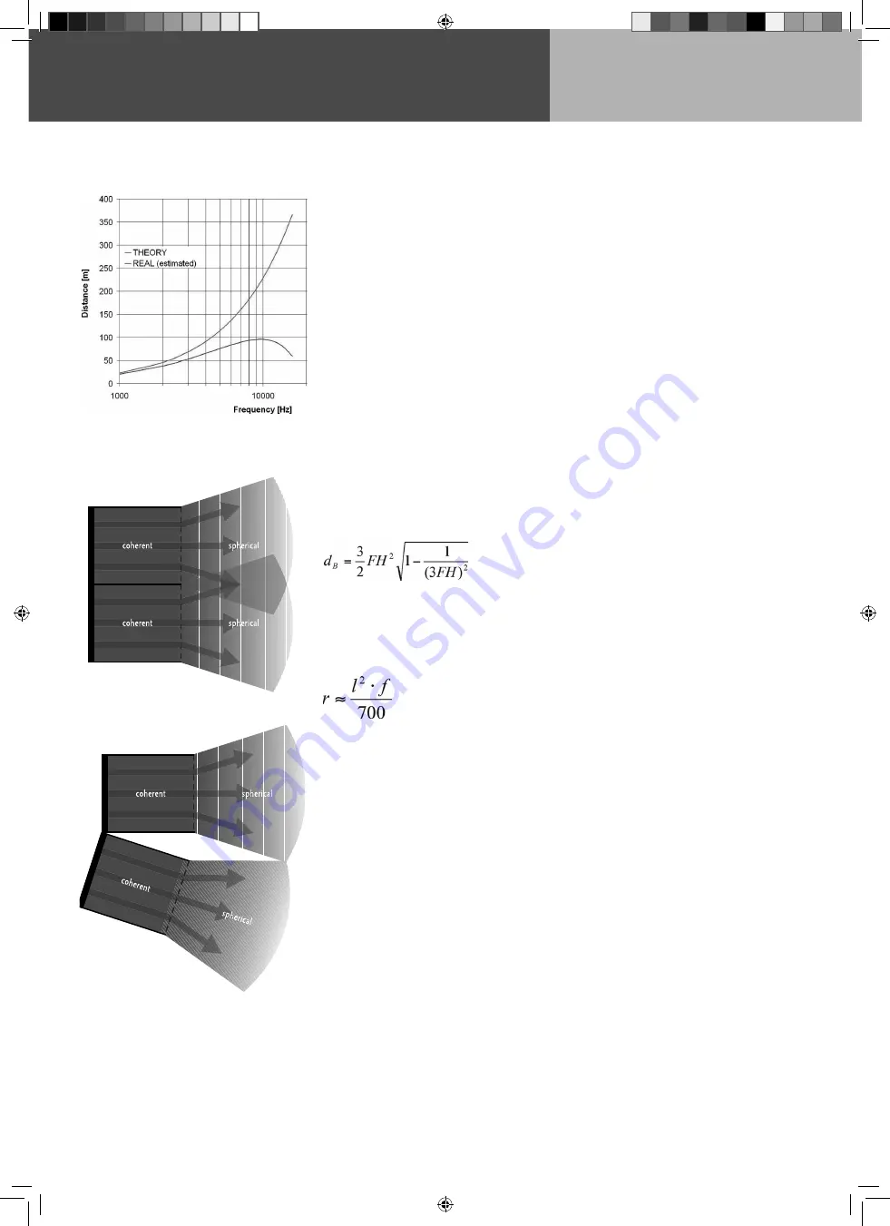
According to the aforementioned formulae, at a fre-
quency of 16 kHz the near field of a line array with
the length of 4 m extends out to 380 m!
Anyone who has heard a line array of comparable
size perform is sure to confirm that this great a
range cannot be attained in a real-world scenario.
The fact is that these values must be scaled down
substantially (see Fig. 1). Consequently, the afore-
mentioned formulae for a continuous line source
are more theoretical in nature.
Why these differences between theory and practice,
and why does a cylindrical wave transition into a
spherical wave front rather than diffuse infinitely?
The answer is quite simple in view of the molecular
structure of air. Air molecules offer frictional resis-
tance, impeding the sound wave's diffusion.
Some sound molecules drift outwards when the
wave's impact excites inert molecules at its fringes.
The cylindrical wave front's keen edges are smoothed
by degrees, gradually transforming the cylindrical
wave into a spherical wave front.
In mathematical terms, this can be described as
a sound vector pointing slightly outward at its
fringes. Because the velocity of propagation remains
constant, the cylindrical wave slowly tran-sition into
a spherical wave.
Technical literature describes the molecular frictional
resistance of air as atmospheric absorption of sound,
which increases exponentially as the frequency rises.
Accordingly, frictional resistance is greater at higher
frequencies, meaning that at higher frequencies,
the transition described occurs at a closer distance
(or smaller ratio).
Similar effects have been observed in analog tech-
nology where a square signal is smoothed by a
low-pass filter. It can be said that at some point
the signal regains a sine-like form.
Values that are possible in theory are again reduced
in practice because the line source is not in fact
continuous in the high frequency range; instead,
it is composed of individual segments. Even with
the most painstaking effort, it is impossible to prevent
interference with or drop-outs of the continuous line
source in practical applications because housings
and edge diffraction inevitably cause some interfe-
rence.
Furthermore, in theory this continuous line source
would always be linear! However, gaps are created
in the air when an array is curved, tearing the line
source apart and further reducing the range.
In order to preclude the phenomenon of gaps created
by curving, a line array would have to consist of very
many individual elements (N=>00), which unfortu-
nately is practically infeasible (see Fig. 2 a, 2 b).
An effort to take these deficiencies into account led
to a next generation line array, with the following
section examines.
Consequently, all the aforementioned formulae
concerning a continuous line source are purely
theoretical nature and must be qualified conside-
rably in practical applications.
Figure 1: Comparison of a 4 m array’s near-to-far field
transition in theory and practice
Fig. 2 a: Continuous line source
Fig. 2 b: Gap due to curving
co_coco_BDA_de_engl_2.indd 6
18.09.2006 17:08:49


