Manual
COHEDRA
®
& COHEDRA
®
Compact
5 Creating a COHEDRA
®
Configuration for
a Project
To create a COHEDRA® configuration for a project,
go to the Setup panel after entering project data,
room data and audience areas.
5.1 Defining the
Simulation's Bandwidth
Before you begin setting up a COHEDRA
®
configuration, click Continuous at the top center
of your screen to select a continuous sound level
simulation. This is the threshold level – the highest
level attained by the COHEDRA
®
system without
triggering the DFC's peak limiters. The readout
automatically changes from Averaging to Broadband
when you select Continuous because continuous
sound level simulations always use a broadband
signal with a spectrum similar to pink noise. Click
A-Weighted to select the A evaluation option for the
sound level simulation.
5.2 Entering COHEDRA
®
Array
Specifications
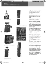
Select Cradle Pick Point and type the x coordinates
into the X box and the projected height of the pick
point for the COHEDRA
®
array in the Y box.
Both values are measured from the predetermined
reference point.
Note:
As a rule, the greater the height (altitude) of
the COHEDRA
®
array, the more uniform sound
dispersion will be.
If under exceptional circumstances you are unable
to fly the COHEDRA
®
array and are compelled
to set it up on the ground, select this option by
clicking Ground Stacked. When selected, a check-
mark appears in the box next to Ground Stacked
and the COHEDRA
®
array presented in the side
view is flipped so that the flight frame is on the
bottom. In this case, enter the height of flight frame
that is now below the COHEDRA
®
array into the Y
box under Cradle Pick Point.
In the Total Mid/High box, select the number
of enclosures that you want to employ in your
configuration. The premise in CAPS is that CDR 208
S and CDR 208 T enclosures are distributed equally.
On the one hand, the COHEDRA
®
array produces
a higher sound level with a greater number of
COHEDRA
®
enclosures. On the other, a certain
number of COHEDRA
®
enclosures is necessary
to achieve the required vertical angle of radiation
and sufficient spread in the near field.
This means that for some projects, you may require
more COHEDRA
®
enclosures than are strictly
necessary to achieve the desired sound level.
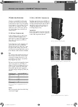
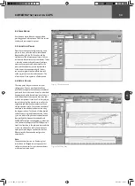
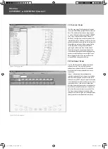
In the side view, you'll now see a view of the room
with the audience areas and a COHEDRA
®
array
consisting of the number of enclosures that you
have determined. Note that lines run from every
enclosure (main axis); these tools are there to
help you align speakers. Values appear at the point
where an aiming line meets an audience area. They
indicate the distance from the respective point to
the given enclosure in meters, and the given delay
in milliseconds.
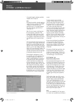
In Box 1 at the left edge of the screen, click Angles
and enter the vertical angle of the top enclosure to
the neighboring enclosure so that it is aimed toward
the rearmost row of the rearmost or uppermost
audience area. This is done to prevent undesirable
reflections from bouncing off the back wall. Or
you can click Auto under Box 1 to have CAPS
automatically adjust this angle for you. The angle
of the top enclosure and its alignment remains
unchanged for all further settings. This also applies
to settings that change the array's focal point.
You have another option alongside entering the
angle directly: Click Pin Point to the right of Box 1
to determine the vertical angle of the top enclosure
by entering the pick-point on the flight frame.
When you have determined a pick-point using
this method, it remains unchanged for all further
settings, although this does change the alignment
of the top enclosure when the array's focal point is
changed.
co_coco_BDA_de_engl_2.indd 56
18.09.2006 17:09:16

