C18UE001-1804
4.
Zero-Position
4.1
Zero Position Setting
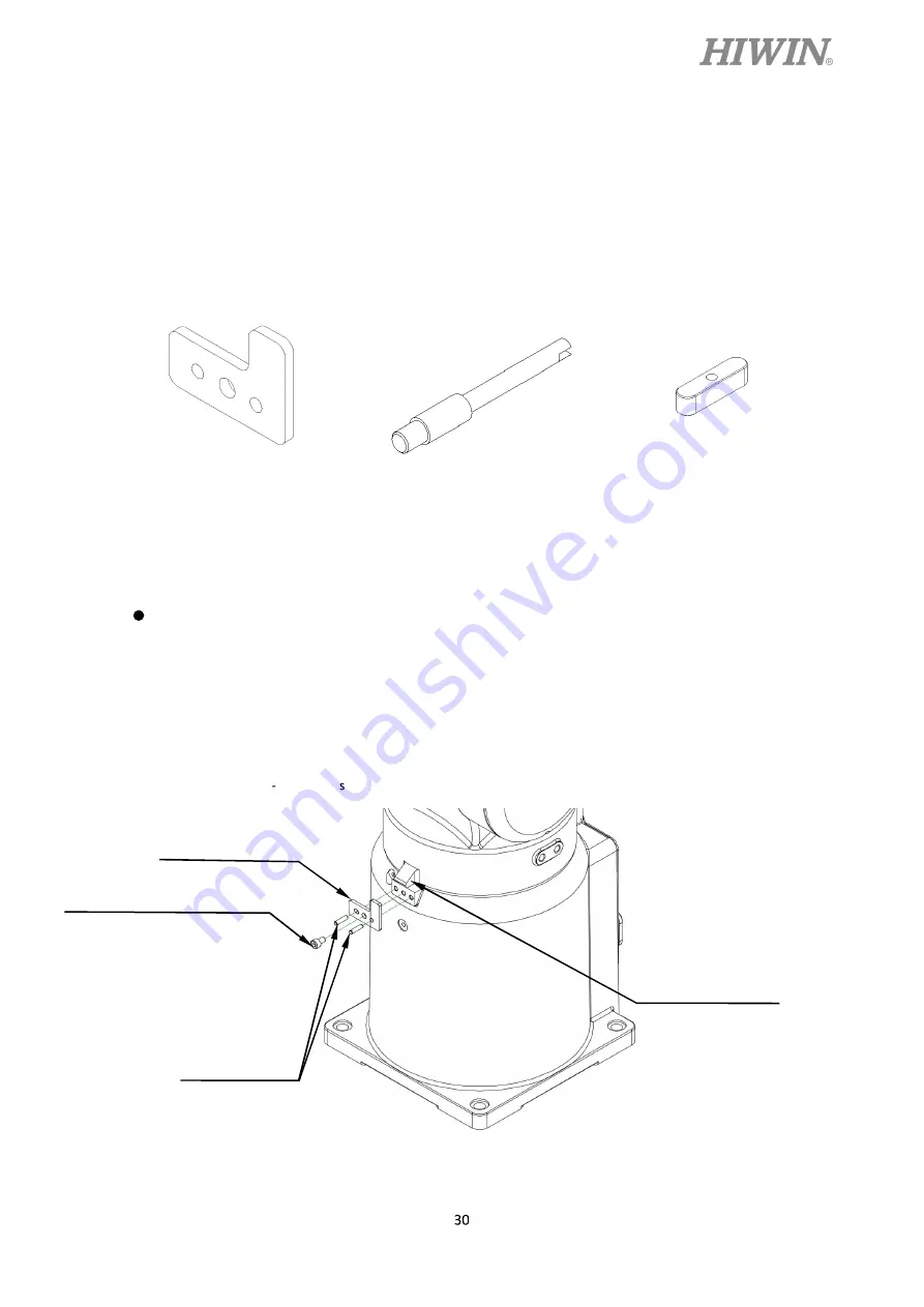
The calibration tools for setting Zero-position are shown in Figure 4-1. The robot is
adjusted to the minimum speed during the calibration, and aligns the pinhole with the
calibration tool to set up the Zero-position. The procedure of resetting Zero-position with the
calibration tools is shown below.
Figure 4-1(a) 4-1(b) 4-1(c)
Calibration tool (A) Calibration tool (B) Calibration tool (C)
Figure 4-1 The calibration tool set
J1-axis Zero-position setting
Step1.
Secure the calibration tool (A) on J1-axis by using positioning pin and screws.
Step2.
Operate J1 at low speed to align the positioning surface of J2 with the calibration
tool (A).
Step3.
Finish calibration and remove the calibration tool (A).
Step4.
Clear encoder by HRSS. (Refer to page 34)
Step5.
Zero position etting of J1-axis is completed.
Figure 4-2 Illustration of J1-axis Zero-position setting
Hexagon socket cap screw
M5
x
0.8P
x
6L (Nickel plated)
Positioning pin
Calibration tool(A)
Positioning surface
Содержание RT605 Series
Страница 1: ......
Страница 14: ...C18UE001 1804...
Страница 26: ...C18UE001 1804 Figure 2 4 RT605 909 GB Motion range...
Страница 50: ......
Страница 51: ......


