C21UE102-2110
70
3.6.1.
CC-LINK Interface (optional)
Description:
The following figure shows the pin assignment of CC-LINK controller.
(a)RC4-A
(b)RC4
Figure 3-8 CC-LINK connector of RC4 controller
Figure 3-9 Illustration of CC-LINK connector and pin define
Table 3-5 Definition of CC-LINK pin
Pin
Signal
Description
1
DA
Data A
2
DB
Data B
3
DG
Data Ground
4
SLD
Shield
5
FG
Field Ground
CC-Link
Содержание RC4
Страница 1: ...www hiwin tw User Manual Robot Controller RC4 Series Original Instruction ...
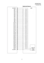
Страница 64: ...C21UE102 2110 62 D SUB 44P INPUT NPN OUTPUT NPN ...
Страница 65: ...C21UE102 2110 63 D SUB 44P INPUT PNP OUTPUT PNP ...
Страница 77: ...C21UE102 2110 75 ...
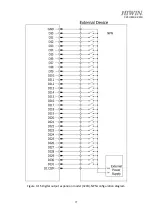
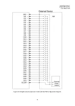
Страница 79: ...C21UE102 2110 77 Figure 3 15 Digital output expansion model 32CH NPN configuration diagram ...
Страница 80: ...C21UE102 2110 78 Figure 3 16 Digital output expansion model 32CH PNP configuration diagram ...
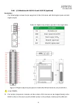
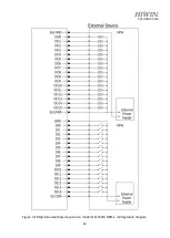
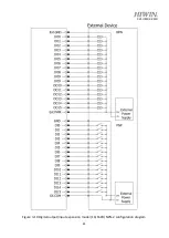
Страница 82: ...C21UE102 2110 80 Figure 3 18 Digital output input expansion model 16 16CH NPN 1 configuration diagram ...
Страница 83: ...C21UE102 2110 81 Figure 3 19 Digital output input expansion model 16 16CH NPN 2 configuration diagram ...


