HITEC OPTIC 6 Sport Скачать руководство пользователя страница 27

Page  51

Page 52

P. CV (Pitch Curve)

Setting Up The Throttle Curve

Like the throttle curve described previously, pitch curves are tied to the position of the throttle / collective stick, just as described in the Throttle 
curve section.
Setup instructions are the same as those for throttle curve, except that you may also input a curve for the throttle hold/ST3 flight mode. 
If you are a beginner, don't worry about throttle HOLD for awhile. 
You can get a linear response by making the five settings line up as shown above. But if you want another shape, you're free to do it. 
You can "flatten out" or "soften" the curve around hover, which is handy for making the control less sensitive there.

Inputting The Pitch Curve Values

1. Press one of the Up Down EDIT buttons until the P.CV window appears. 
    The default is for a linear curve, a straight line from 0 to 100% passing through 50% at hover (center).
2. Be sure you're in the desired flight Modes by moving the Flt. 
    Mode switch (SW-3) to its proper position. Remember, you can input separate, independent throttle 
    curve settings for each separate idle-up mode.
3. You begin a point 1, which will be blinking. This is the idle position and will have a default value of 0%. 
    Press the DATA +Increase or -Decrease button to change the setting to your desired value.
4. When you're finished with Point 1, move to the next point with the CURSOR Right button. 
    The number 2 position will be blinking and that indicates you are setting the value for Point 2. 
    Note that the function is inhibited (Inh) to start with. If you leave it, you get a straight line from points 1 to 3. Otherwise, you can change this 
    setting with the DATA +Increase or -Decrease buttons.
5. Repeat this procedure for Points 3, 4, and 5 by pressing the CURSOR Right button, then adjusting as desired by pressing the CLEAR button, 
    and then changing the value with the DATA “+” or “-” button.
6. When you've completed the settings for the first flight mode (NOR), test fly your model. 
    When you're satisfied with the settings, use them as a basis for the other flight Modes. 
    Flip the switches as necessary to get into the new mode, verify on the display that you are in the desired flight mode, then set all the five 
    points in by going through the steps given previously

1. Press one of the Up Down EDIT buttons until the T.CV window appears. The default is for a linear 
    curve, a straight line from 0 to 100% passing through 50% at hover (center, point 3).
2. Be sure you're in the desired flight Mode by moving the Flt. 
    Mode (SW-1) switch to its proper position. Remember, you can input separate, independent throttle 
    curve settings for each separate idle-up mode (except for ST3, throttle hold)! 
3. You begin a point 1, which will be blinking. This is the idle position and will have a default value of 0%.  
    Press the DATA +Increase or -Decrease button to change the setting to your desired value, 
    try about 15 to 20% to start with. 
4. When you're finished with Point 1, move to the next point    with the CURSOR Right button. 
    The number 2 position will be blinking and that indicates you are setting the value for Point 2. 
    Note that the function is inhibited (Inh) to start with. 
    If you leave it, you get a straight line from points 1 to 3. 
    Otherwise, you can change this setting by pressing the CLEAR button, and then changing the value 
    with the DATA +Increase or -Decrease button.

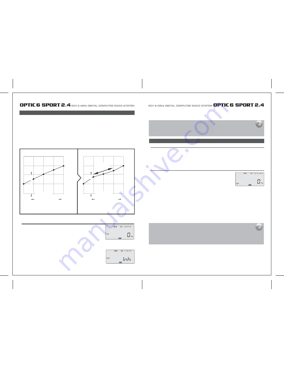
T.CV (Throttle Curve)

The throttle & pitch curves are tied to the position of the Throttle / Collective stick, and are specified at five points labeled 1through 5 below. 
These "curves" are really straight lines connecting the settings at the five points, and are defined by assigning servo movement percentages 
to five positions of the left stick:
Lowest stick position = Point 1, 
1/4-up stick position = Point 2,
Half-stick = Point 3,
3/4 position = Point 4,
Top stick position = Point 5.

With the numbers defined as shown, the servo would move 50% of full travel to one side at low  collective stick position, and 50% of full travel 
to the other side at high stick position.

You can get a linear response by making the five settings line up 
as shown above. But if you want another shape, you're free to do it.  

100%

75%

75%

50%

60%

50%

40%

25%

25%

0%

1

2

3

4

5

Low           Collective Stick          High

Curve Point

Example of Five-Point Curve

Soften Near Hover

Shallower
Slope in this 
region 

Servo Response

100%

75%

75%

50%

63%

50%

25%

38%

25%

0%

1

2

3

4

5

Low            Collective Stick           High

Curve Point

Example of Five-Point Curve

Servo Response

5. Repeat this procedure for Points 3, 4, and 5 by pressing the CURSOR Right button, then adjusting as desired with the DATA “+” or “-” buttons.
6. When you've completed the settings for the Throttle curves in the first flight mode (NOR), go the Pitch Curve section and setup the pitch 
    curves for the NOR mode. 

Setting "Idle-Up" curves up in other flight modes

After you learn to fly well in the "NOR" mode, consider programming the "Idle-Up" curves for doing 
more advanced aerobatic or 3D maneuvers. Use the settings in the NOR curve as a basis for the 
other flight modes used by advanced heli pilots.

Where are the Hover Throttle and Hover Pitch controls?

Experienced Heli pilots may be looking for the hover throttle and hover pitch controls on 
the Optic 6 Sport 2.4.  
Stop looking for it, there aren't any! 
Fine adjustment of  hover throttle and pitch can be done at the number 3 or middle curve point on both 
the throttle and pitch curves menu. 

P. CV (Pitch Curve)

You can "flatten out" or "soften" the curve around hover as
shown here. 
This is handy for making the control less sensitive around hover.

Содержание OPTIC 6 Sport

Страница 1: ...AL COMPUTER RADIO SYSTEM SYSTEM 2 4 Function Assignable Switches Easy to Read LCD Screen Bulit in Hitec AFHSS 2 4GHz System INSTRUCTION MANUAL 0678 6CH 2 4GHz DIGITAL COMPUTER RADIO SYSTEM 2 4 Made in...

Страница 2: ...C 6 SPORT 2 4 is your first programmable radio control transmitter you re probably feeling a bit overwhelmed by all the buttons and switches on the case and the cryptic symbols that appear on the radi...

Страница 3: ...emperature extremes For protection wrap the receiver in the provided Flight Preserver foam rubber or use some other vibration absorbing materials If your flying near bodies of water it s also a good i...

Страница 4: ...ally power on the STUDENT transmitter Though it is powered on the STUDENT transmitter will not transmit the radio signal as long as the trainer cable is connected properly 1 To use the trainer system...

Страница 5: ...n their vicinity Flying Safety Stick Length Adjustment You may adjust the stick tension of your sticks to provide the feel that you like for flying To adjust your springs you ll have to remove the rea...

Страница 6: ...of using this function whenever you are carrying your model to the flight line LOCK button KEEP YOUR HANDS AWAY FROM THE PROPELLER OR ROTORS EVEN AFTER ENABLING THE LOCK FUNCTION A RADIO GLITCH COULD...

Страница 7: ...with Dual LED indicator has two colored LEDs blue and red for status indication and for set up process indication of 2 4GHz system This function button can be used for Link ID Setting process between...

Страница 8: ...on is easy and simple insert the antenna into the supported Antenna holder and stick it to the desired spot you wish to install Optima 6 Receiver Features Optima Receiver Connection Diagrams Follow th...

Страница 9: ...e are available 2 4GHz channels that can be used by your Hitec AFHSS 2 4 system The following will explain how Normal Mode and Scan Mode use the channels Normal Mode In this mode the receiver transmit...

Страница 10: ...switch to Scan Mode noted by the blue and red LED and one beep Switching from Normal Mode to Scan Mode 1Sec 3Sec 3Sec Turn on transmitter then the receiver You will hear two short beep sound for Scan...

Страница 11: ...ivers into other aircraft to be controlled by your Aurora Note both module and receiver need to re boot turn the power off and back on FAIL SAFE and Hold Mode FAIL SAFE Setup If you use the FAIL SAFE...

Страница 12: ...a regulator set up or a commercially available BEC with enough capacity 3A or more capacity is recommended The SPC system was partially created to be integrated into future Hitec telemetry system devi...

Страница 13: ...symbol in the black box at the bottom of the screen indicates which switch SW1 or SW3 needs to be reset to Normal Rx Ch ACRO GLID HELI Aileron Aileron Roll Cyclic One or Right Flaperon FLPN ON or Rig...

Страница 14: ...information on using the timer function Otherwise move down to the next menu item 5 Select the control s Mode configuration 6 Select the signal shift Under the word MODE the number 2 is blinking by d...

Страница 15: ...itial setup menu Go ahead and switch the transmitter on you are now in the standard operating screen In the upper left hand corner it will say ACRO and to the right there will be a large number tellin...

Страница 16: ...direction The EPA function is normally used to prevent any servos from binding at the ends of their travel 1 To set the RIGHT TURN aileron motion which is upward on the right wing and downward on the...

Страница 17: ...blinking if it isn t already by default The default value showing on the screen should be 100 but notice the extra little zero next to the 100 This indicates that the rate is this value 100 when the s...

Страница 18: ...o servos simultaneously This is especially useful if you are using two elevator servos one to each half of the elevator In flight if the elevator needs to be trimmed you can make the adjustment with t...

Страница 19: ...a rudder control to the aileron stick movement refer to the Aileron Rudder mix on page 26 Use a small percentage of mix for coordinated turns or set it up at 100 mix if your plane does not have ailero...

Страница 20: ...buttons simultaneously Now we are ready to feed in values for the ailerons and elevator for pitch compensation when you pull the switch toward you You could of course choose to activate the mode with...

Страница 21: ...der the default value of 100 If it isn t you can return to the default value immediately by pressing the Clear button Next to the 100 a 0 indicates that switch SW 2 is in the 0 position if it isn t pu...

Страница 22: ...back to this section when you are ready to begin the setup 1 Start with the correct model type GLID in the Initial Setup Menu 2 Access the main programming menu then use the REV function and make sure...

Страница 23: ...ints inside circle Too much coupling or differential Reduce one or both ADIF Aileron Differential Initial Menu Feature Review for GLID Programming The following item is located in the Initial Menu as...

Страница 24: ...on CH 6 to 75 of their travel If you have two flap servos they should be connected with a Y harness to the channel 6 slot on the receiver 4 Finally curser to CH 2 and set the elevator travel value so...

Страница 25: ...smitters in the gyro s manual 7 Program 35 EXPO values for Roll Ch 1 and Pitch Ch 2 8 After your heli is all ready to fly put it on a shelf and go get an R C flight simulator program for your PC Spend...

Страница 26: ...this menu you can program specific control functions and the value the amount of servo travel for the particular model helicopter you selected earlier in the initial setup menu Go ahead and switch th...

Страница 27: ...ttle hold 3 You begin a point 1 which will be blinking This is the idle position and will have a default value of 0 Press the DATA Increase or Decrease button to change the setting to your desired val...

Страница 28: ...type does contain the SWAH menu The swash default settings are shown below The Throttle Hold function moves the engine throttle servo to a selected position near idle and disengages it from the throt...

Страница 29: ...aileron 7 If all the servos tilt the swash aft with up elevator stick go to the next step If they tilt the swash forwards press the CURSOR Right button once to get to the elevator setting menu the arr...

Страница 30: ...E CH5 ON INH ON INH ON INH NOR ST1 ST2 ST3 V TAL A R E F CROW CAMB ADIF FLT C TIMER MODE ON INH TRM 0 1 0 1 D R EXP S TRM S REV ELEV CH2 ELEV CH4 RUDD CH4 RUDD CH2 MODEL TYPE HELI SFT N P MODEL NAME 0...

Отзывы: