HITEC OPTIC 6 Sport Скачать руководство пользователя страница 23

Page  43

Page 44

ADIF  (Aileron Differential)

Activating Flaperons

Creating Aileron Differential

STCK  (Throttle Stick or Switch) 

If your glider uses an electric motor for self-launching, the GLID programming baseline thoughtfully allows you to retain throttle control even 
if you opt to activate the CROW function on the left-hand joystick/throttle stick. To make this change in order to have a proportional CROW 
function, follow these two steps: 

1. Be sure MAS and "1" are blinking. Now, as you hold the stick 
    to the left, reduce the value with the -DATA button to 50%.  
2. Use the Right CURSOR to get "SLV 1" blinking and then 
    reduce the travel value to 50% as you hold the stick to the 
    right. Now your ailerons are programmed with 50% differential. 
 

This is the Main Function Menu screen (instead of FLPN in the ACRO baseline) where you can 
activate the aileron servo plugged into channel 5 to create flaperons. It is also where you can create 
aileron differential:  Being able to adjust the ailerons so they can travel more in one direction 
(usually about twice as much UP movement as DOWN) is an especially important quality for sailplanes 
as differential reduces the "parasitic" drag due to a yawing fuselage and unnecessary aileron travel. 

Using the right-hand EDIT button, scroll down to the ADIF screen and activate the differential 
programming by pressing both DATA buttons. 
The "MAS" and CH "1" should now be blinking and CH 5 "SLV" holding steady 
(indicating the master servo is channel one and its slave is channel 5). 
The default values for both left-hand stick throw (L/U) and right-hand stick (R/D) should be 100%. 
Now, when the right wing's aileron moves up and down with the stick throw, the left-wing aileron 
follows suit (but in the opposite direction).
If you activate the CROW function and/or the Elevator-to-Flap mix, both ailerons will move in 
unison as Flaperons.

Note: You must activate this program to create flaperons before you can set up Elevator-to-Flap, 
          Camber, or Crow mixing functions.

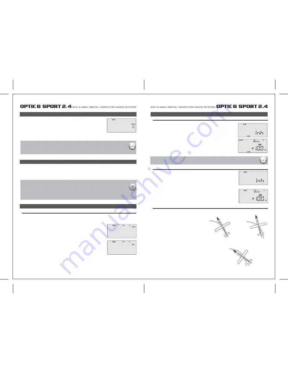
Nose Points outside Circle

increase coupling and/or
differential

Coordinated turn

fuse lines up with turn direction
(don't change anything!)

Nose Points inside circle

Too much coupling or differential.
Reduce one or both.

ADIF  (Aileron Differential)

Initial Menu Feature Review for GLID Programming

The following item is located in the Initial Menu as described on page 13 -15. We will review it here.

Select the Model type baseline: In the second menu screen, the programming baseline of 
ACRO, GLID, or HELI will be blinking. 
Since we are setting up a Sailplane, select GLID by scrolling to it with a CURSOR button. 
Push down both DATA buttons simultaneously to tell the program to accept the choice-you should 
hear the transmitter beep twice in acknowledgement. 

Important Note: Do you have a "flying wing" glider?

In the GLID mode the ELVN program is rendered unavailable-if  your glider is a flying wing, use the ACRO 
mode to set it up. 

Model Setup Main Menu Programming

STCK  (Throttle Stick or Switch) 

In the GLID programming baseline three new functions appear that are not available in the ACRO mode: A CROW function allows you to 
program a descent control in which both ailerons move upward while the flaps move downward; an ADF function creates flaperons and 
aileron differential and a STCK function moves the throttle of your glider's motor off the left-hand joystick and places it on the switch 
SW-1 on the upper left-hand corner of the transmitter case (which frees up the joystick to proportionally control the "CROW" function.) 

1. Go into the Main menu and scroll down to the STCK screen. 
    The default setting puts the throttle on the left-hand joystick. 
2. To put the throttle on the switch SW-1, push down both DATA buttons simultaneously and watch as 
    the screen displays "SW 1". Now, when you move this switch toward you from "0" to "1", the motor
    will come on with full power

At this point you should have selected GLID in the Initial Setup Menu as the baseline programming 
for the model you wish to set-up. In the text that follows, we will review and explain the Model Setup 
Menu items specific to the GLID Menu for setting up your glider.

For those GLID features common to ACRO, refer to their description within the ACRO section to set up 
your model's basic functions (such as servo reverse and end point travel).  

Now let's reduce the downward travel of each aileron to about half that of the upward travel 
(a good starting point for setting up differential on a typical sailplane:

Содержание OPTIC 6 Sport

Страница 1: ...AL COMPUTER RADIO SYSTEM SYSTEM 2 4 Function Assignable Switches Easy to Read LCD Screen Bulit in Hitec AFHSS 2 4GHz System INSTRUCTION MANUAL 0678 6CH 2 4GHz DIGITAL COMPUTER RADIO SYSTEM 2 4 Made in...

Страница 2: ...C 6 SPORT 2 4 is your first programmable radio control transmitter you re probably feeling a bit overwhelmed by all the buttons and switches on the case and the cryptic symbols that appear on the radi...

Страница 3: ...emperature extremes For protection wrap the receiver in the provided Flight Preserver foam rubber or use some other vibration absorbing materials If your flying near bodies of water it s also a good i...

Страница 4: ...ally power on the STUDENT transmitter Though it is powered on the STUDENT transmitter will not transmit the radio signal as long as the trainer cable is connected properly 1 To use the trainer system...

Страница 5: ...n their vicinity Flying Safety Stick Length Adjustment You may adjust the stick tension of your sticks to provide the feel that you like for flying To adjust your springs you ll have to remove the rea...

Страница 6: ...of using this function whenever you are carrying your model to the flight line LOCK button KEEP YOUR HANDS AWAY FROM THE PROPELLER OR ROTORS EVEN AFTER ENABLING THE LOCK FUNCTION A RADIO GLITCH COULD...

Страница 7: ...with Dual LED indicator has two colored LEDs blue and red for status indication and for set up process indication of 2 4GHz system This function button can be used for Link ID Setting process between...

Страница 8: ...on is easy and simple insert the antenna into the supported Antenna holder and stick it to the desired spot you wish to install Optima 6 Receiver Features Optima Receiver Connection Diagrams Follow th...

Страница 9: ...e are available 2 4GHz channels that can be used by your Hitec AFHSS 2 4 system The following will explain how Normal Mode and Scan Mode use the channels Normal Mode In this mode the receiver transmit...

Страница 10: ...switch to Scan Mode noted by the blue and red LED and one beep Switching from Normal Mode to Scan Mode 1Sec 3Sec 3Sec Turn on transmitter then the receiver You will hear two short beep sound for Scan...

Страница 11: ...ivers into other aircraft to be controlled by your Aurora Note both module and receiver need to re boot turn the power off and back on FAIL SAFE and Hold Mode FAIL SAFE Setup If you use the FAIL SAFE...

Страница 12: ...a regulator set up or a commercially available BEC with enough capacity 3A or more capacity is recommended The SPC system was partially created to be integrated into future Hitec telemetry system devi...

Страница 13: ...symbol in the black box at the bottom of the screen indicates which switch SW1 or SW3 needs to be reset to Normal Rx Ch ACRO GLID HELI Aileron Aileron Roll Cyclic One or Right Flaperon FLPN ON or Rig...

Страница 14: ...information on using the timer function Otherwise move down to the next menu item 5 Select the control s Mode configuration 6 Select the signal shift Under the word MODE the number 2 is blinking by d...

Страница 15: ...itial setup menu Go ahead and switch the transmitter on you are now in the standard operating screen In the upper left hand corner it will say ACRO and to the right there will be a large number tellin...

Страница 16: ...direction The EPA function is normally used to prevent any servos from binding at the ends of their travel 1 To set the RIGHT TURN aileron motion which is upward on the right wing and downward on the...

Страница 17: ...blinking if it isn t already by default The default value showing on the screen should be 100 but notice the extra little zero next to the 100 This indicates that the rate is this value 100 when the s...

Страница 18: ...o servos simultaneously This is especially useful if you are using two elevator servos one to each half of the elevator In flight if the elevator needs to be trimmed you can make the adjustment with t...

Страница 19: ...a rudder control to the aileron stick movement refer to the Aileron Rudder mix on page 26 Use a small percentage of mix for coordinated turns or set it up at 100 mix if your plane does not have ailero...

Страница 20: ...buttons simultaneously Now we are ready to feed in values for the ailerons and elevator for pitch compensation when you pull the switch toward you You could of course choose to activate the mode with...

Страница 21: ...der the default value of 100 If it isn t you can return to the default value immediately by pressing the Clear button Next to the 100 a 0 indicates that switch SW 2 is in the 0 position if it isn t pu...

Страница 22: ...back to this section when you are ready to begin the setup 1 Start with the correct model type GLID in the Initial Setup Menu 2 Access the main programming menu then use the REV function and make sure...

Страница 23: ...ints inside circle Too much coupling or differential Reduce one or both ADIF Aileron Differential Initial Menu Feature Review for GLID Programming The following item is located in the Initial Menu as...

Страница 24: ...on CH 6 to 75 of their travel If you have two flap servos they should be connected with a Y harness to the channel 6 slot on the receiver 4 Finally curser to CH 2 and set the elevator travel value so...

Страница 25: ...smitters in the gyro s manual 7 Program 35 EXPO values for Roll Ch 1 and Pitch Ch 2 8 After your heli is all ready to fly put it on a shelf and go get an R C flight simulator program for your PC Spend...

Страница 26: ...this menu you can program specific control functions and the value the amount of servo travel for the particular model helicopter you selected earlier in the initial setup menu Go ahead and switch th...

Страница 27: ...ttle hold 3 You begin a point 1 which will be blinking This is the idle position and will have a default value of 0 Press the DATA Increase or Decrease button to change the setting to your desired val...

Страница 28: ...type does contain the SWAH menu The swash default settings are shown below The Throttle Hold function moves the engine throttle servo to a selected position near idle and disengages it from the throt...

Страница 29: ...aileron 7 If all the servos tilt the swash aft with up elevator stick go to the next step If they tilt the swash forwards press the CURSOR Right button once to get to the elevator setting menu the arr...

Страница 30: ...E CH5 ON INH ON INH ON INH NOR ST1 ST2 ST3 V TAL A R E F CROW CAMB ADIF FLT C TIMER MODE ON INH TRM 0 1 0 1 D R EXP S TRM S REV ELEV CH2 ELEV CH4 RUDD CH4 RUDD CH2 MODEL TYPE HELI SFT N P MODEL NAME 0...

Отзывы: