


Page 47
Page 48
Select the Model Type Baseline:
Heli Swash Plate:
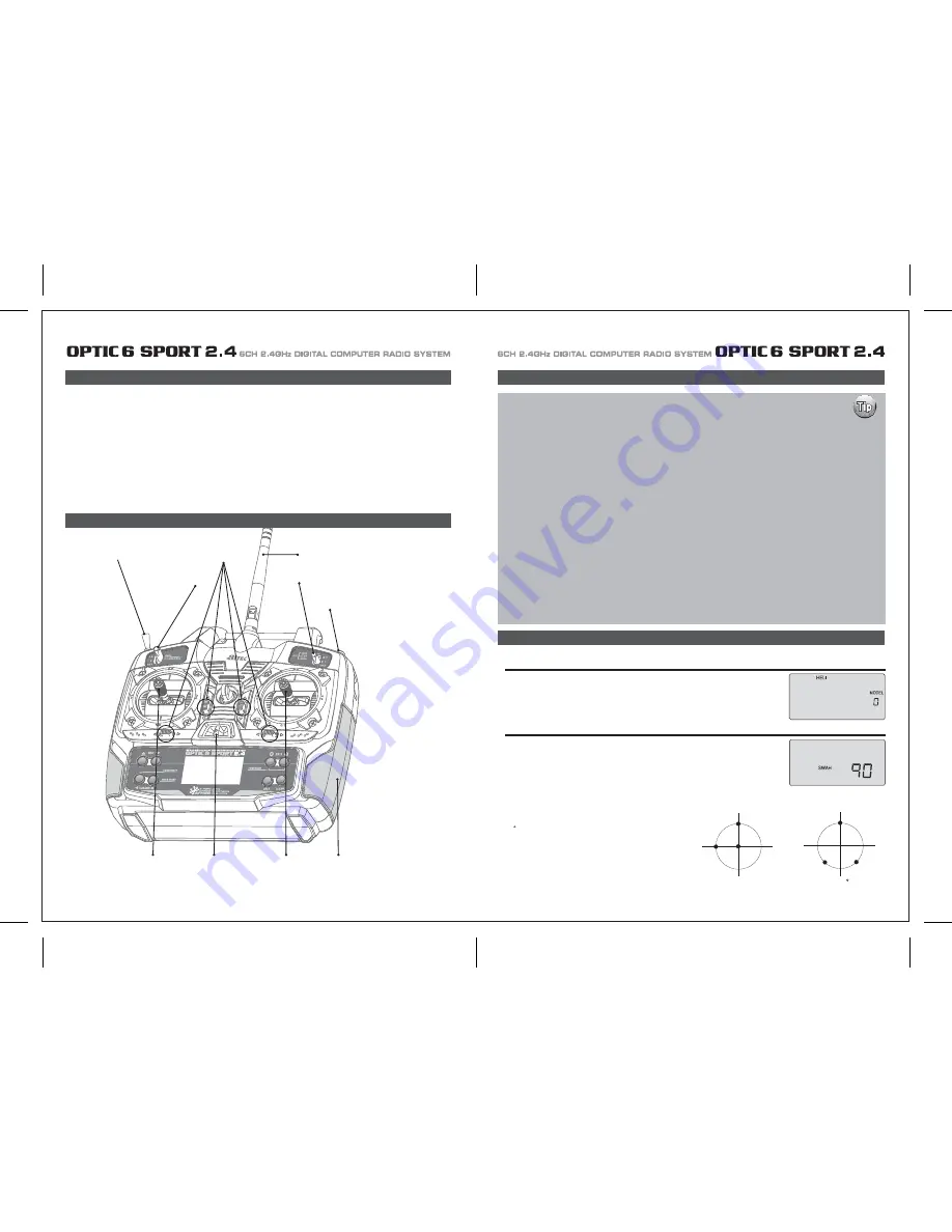
Optic 6 Sport Heli In-Flight Controls
This section covers the Optic 6 Sport programming that is specific to the HELI mode for flying a model Helicopter.
To avoid duplication of text within the manual we suggest that if you have not already read the following you refer to this previously
shown information in the front of the manual.
- Introducing the Optic Sport
- If You are New to Computerized RC Transmitters
- Charging the Batteries
- Flying Safely
- Mode 1 Configuration
- Flying Field info
- Frequency Control
- Optic sport Programming Switches and Buttons
- Initial Setup Menu Programming
- Transmitter Displays and Messages
Please note: To reference all other Optic 6 Sport programming instructions not specific to the HELI menu refer to the Initial Setup
menu on page 13 and the ACRO Model Setup menu starting on page 17.
Optic 6 Sport Manual for Helicopters
This figure shows the assignments for a Mode 2 system as supplied by the factory.
Note that some of the functions will not operate until activated in the mixing menus.
If this is your first Heli
If this is your first model Helicopter, here are a few tips that will streamline your experience in
programming it.
This will make more sense after you read through the manual. Refer back to this section when
you are ready to begin the setup:
1. Start with the correct Swash plate setting for your Heli in the Initial Setup Menu.
2. Then use the REV function, and make sure all the servos are moving in the proper direction.
3. After centering the servo arms manually as close as you can, use the S.TRM or sub-trim function to
center the servos.
4. Set your servo end points with the EPA function.
5. Read through the section on throttle and pitch curves and have a go at setting the NOR curves.
Don't worry about Throttle Hold, Flight modes and Idle-up curve "stuff" until you can hover and fly
well in the NOR mode.
6. Work on the gyro set-up. Read about how your gyro interfaces with different transmitters in the gyro's manual.
7. Program -35% EXPO values for Roll, Ch. 1 and Pitch, Ch. 2.
8. After your heli is all ready to fly, put it on a shelf and go get an R/C flight simulator program for your PC.
Spend quality time crashing the virtual heli in the simulator. Using a sim will save you hundreds of dollars
spent on spare parts and countless hours of rebuilding time in the long run.
9. Ready to fly your new Heli? If you are lucky you will know someone that is an experienced model Helicopter
pilot and would be willing to check over your chopper and take it up for its first flight.
This is HIGHLY RECOMMENDED, even if you have to drive a hundred miles to get to this person! If you are
on your own, start slow and use a set of training gear on your model to prevent tip-overs.
Learn to hover first and then transition into forward flight.
Initial Menu Feature Review For HELI Programming
The following two items are located in the Initial Menu as described on page 13-15. We will review them here.
In the second menu screen, the programming baseline of ACRO, GLID, or HELI will be blinking.
Since we are setting up a helicopter, select HELI by scrolling to it with a CURSOR button.
Push down both DATA buttons simultaneously to tell the program to accept the choice-you
should hear the transmitter beep twice in acknowledgement.
If you selected HELI as your model type, this screen will appear allowing you to select between NOR
(Normal 90 degree mechanical) swash plate arrangement or a 120 degree swash plate by pressing one
of the CURSOR buttons. Consult your model's manual to find out which one of these popular swash
formats your heli uses and select it here.
NOR is the standard swashplate where one servo each
performs the collective pitch, elevator, and aileron functions.
120 is intended for three servo swashplates needing special
mixing to get the servos to properly provide the required pitch,
elevator, and aileron functions. The swashplate type 120¡Æ is
also referred to as SN-3
CH1
CH2
CH6
NOR
120
CH2
CH1
CH6
ROTOR TYPE
Trainer/Engine Cut Switch
SW 3
SW 1
Rudder &
Throttle Stick
Aileron &
Elevator Stick
Plastic Side Panel
SW 2
Antenna
Trim Switch
Power Switch
Optic 6 Sport Heli In-Flight Controls


