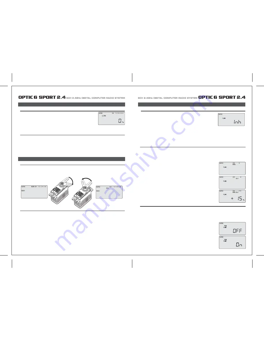
HITEC OPTIC 6 Sport Скачать руководство пользователя страница 18

Page 33

Page 34

S. TRM  (Sub Trim)

Set Up a Throttle Rudder Mix

P. MIX (Programmable Mix)

In this screen you can activate the ability of the Optic 6 Sport to create a custom-made, 
programmable mix of any two servo channels in which one servo is electronically "slaved" to another. 
This is a relatively advanced function.
The program also provides a way to change the value of the response of the slave servo to that of the 
master. 
For example you could slave the elevator servo to the throttle channel so that when you increase 
the throttle, a slight downward movement of the elevator kicks in to automatically compensate for any 
up-pitching due to the increased thrust. 
Another typical mix might be to mix rudder with the throttle to reduce yawing. 
The Optic Sport's mixing program also offers an advanced function (call TRM P MIX) that, when activated, allows both servos to be 
trimmed by the same master servo trim button on the radio case-a useful option when, for example, you are using two servos to control a 
split elevator. 

When you apply throttle to a powerful motor, the resultant torque from the spinning propeller often tends to make the plane yaw to one side 
(usually to the left).
This not only interferes with precision aerobatic maneuvers, but it makes it difficult to keep the model aligned with the runway during a 
full-power takeoff. To reduce the "pilot load" of having to correct the yaw with your left thumb on the rudder stick, you can use the P-Mix 
program function to automatically mix a proportional amount of rudder with an increase of throttle.
Now let's set it up:

P. Mix Trim:

1) Enter the Main Function menu and scroll down to the P MIX screen with the EDIT buttons. 
    Activate the function by pressing both DATA buttons-"Inh" will turn off and the default screen 
    shows "CH" with "MAS" blinking beneath. If, instead, a percentage value is blinking use the 
    right-hand CURSOR button to scroll over until you get this "CH" and "MAS" configuration. 
    One of the servo channel numbers will also be showing-the default is "1".
2) To make the throttle the master channel, push a DATA button to light up "3". 
    Now push the right-hand CURSOR once more: "SLV" will light up with a number. 
    Use a DATA button to change this number to "4". Now the rudder channel is slaved to 
    the throttle channel.
3) Push the CURSOR button again: MAS 3 and a percentage value will be blinking. 
    Use the DATA buttons to set the value of rudder travel to throttle travel-change to a negative 
    value to move the rudder in the opposite direction if necessary. 
    You won't likely need more than 15% to counteract the torque, but only flight-testing will tell for sure.  
  

Set up a double-servo elevator with coordinated trim function

The Optic 6 Sport 2.4GHz offers an unusually sophisticated nuance with its P-MIX function: the ability to trim two servos simultaneously. 
This is especially useful if you are using two elevator servos (one to each half of the elevator). In flight, if the elevator needs to be trimmed, 
you can make the adjustment with the trim button next to the right-hand joystick on the case instead of having to enter the model setup 
programming in order to trim the servos independently.  
Lets set this example up: 

1) Enter the P MIX screen and select the master and slave servos 
    (2 and 5 on this radio for split elevators) and then select the travel value (most likely 100% unless 
    your servo pushrods are not set up exactly the same way). 
2) Now use the Right CURSOR button to move to the P MIX screen where "TRM" is blinking. 
    The default setting is "OFF"-turn it to "ON" by pressing the CLEAR button. 
3) Exit the menu and you now have a split elevator with trim function.

S. TRM  (Sub Trim)

S. REV (Servo Reverse)

This is a programmable function for setting the subtrim values for each of the servos, 
allowing you to make fine adjustments to each individual servo independently of the trim buttons
located on the radio case (which can be adjusted in flight).
We recommend that you first set up the model's servo pushrods so that the control surfaces are as 
centered as possible mechanically (with the transmitter's case-mounted trim buttons digitally centered) 
before attempting to adjust them in the subtrim menu. We also recommend that you try to keep all the 
subtrim values as small as possible. If the values are large, the servo's full range of travel may be restricted.

Setting Sub Trims

S. REV (Servo Reverse)

At this point you must have your plane in front of you and turned on so you can actually see when the control services are in alignment as you 
change the sub-trim value. 

1. Starting with the CH 1 aileron servo, use the DATA buttons to either increase or decrease the subtrim value until the control surface is 
    properly aligned on the model. 
2. Move over to CH 2 with the right-hand CURSOR button and align the elevator in the same way. 
3. Continue by moving to CH 4 and align the rudder, to CH 6 to adjust the aileron servo in channel 6 and to CH 5 to adjust the flap.

When you first turn on your model, you will immediately see whether all the control surfaces are moving in the correct direction when you 
wiggle the controls. 
If any are moving in reverse, you can come to this screen to reverse the throw of the offending servo.

Reversing a Servo

P. MIX (Programmable Mix)

Let's say your elevator is going down when you pull back on the joystick-that is definitely not going to be a good situation when you go to fly 
your plane! To reverse the elevator servo, come to this screen and use a CURSOR button to move over to CH 2 and push both DATA buttons 
simultaneously.. You'll notice that the symbol "NOR" ahead of CH has changed to "REV"-and that the servo is now operating as it should on 
your model. 
If any other servos need to be reversed, CURSOR over to that channel slot and push both DATA buttons simultaneously.

Normal

Reversed

Содержание OPTIC 6 Sport

Страница 1: ...AL COMPUTER RADIO SYSTEM SYSTEM 2 4 Function Assignable Switches Easy to Read LCD Screen Bulit in Hitec AFHSS 2 4GHz System INSTRUCTION MANUAL 0678 6CH 2 4GHz DIGITAL COMPUTER RADIO SYSTEM 2 4 Made in...

Страница 2: ...C 6 SPORT 2 4 is your first programmable radio control transmitter you re probably feeling a bit overwhelmed by all the buttons and switches on the case and the cryptic symbols that appear on the radi...

Страница 3: ...emperature extremes For protection wrap the receiver in the provided Flight Preserver foam rubber or use some other vibration absorbing materials If your flying near bodies of water it s also a good i...

Страница 4: ...ally power on the STUDENT transmitter Though it is powered on the STUDENT transmitter will not transmit the radio signal as long as the trainer cable is connected properly 1 To use the trainer system...

Страница 5: ...n their vicinity Flying Safety Stick Length Adjustment You may adjust the stick tension of your sticks to provide the feel that you like for flying To adjust your springs you ll have to remove the rea...

Страница 6: ...of using this function whenever you are carrying your model to the flight line LOCK button KEEP YOUR HANDS AWAY FROM THE PROPELLER OR ROTORS EVEN AFTER ENABLING THE LOCK FUNCTION A RADIO GLITCH COULD...

Страница 7: ...with Dual LED indicator has two colored LEDs blue and red for status indication and for set up process indication of 2 4GHz system This function button can be used for Link ID Setting process between...

Страница 8: ...on is easy and simple insert the antenna into the supported Antenna holder and stick it to the desired spot you wish to install Optima 6 Receiver Features Optima Receiver Connection Diagrams Follow th...

Страница 9: ...e are available 2 4GHz channels that can be used by your Hitec AFHSS 2 4 system The following will explain how Normal Mode and Scan Mode use the channels Normal Mode In this mode the receiver transmit...

Страница 10: ...switch to Scan Mode noted by the blue and red LED and one beep Switching from Normal Mode to Scan Mode 1Sec 3Sec 3Sec Turn on transmitter then the receiver You will hear two short beep sound for Scan...

Страница 11: ...ivers into other aircraft to be controlled by your Aurora Note both module and receiver need to re boot turn the power off and back on FAIL SAFE and Hold Mode FAIL SAFE Setup If you use the FAIL SAFE...

Страница 12: ...a regulator set up or a commercially available BEC with enough capacity 3A or more capacity is recommended The SPC system was partially created to be integrated into future Hitec telemetry system devi...

Страница 13: ...symbol in the black box at the bottom of the screen indicates which switch SW1 or SW3 needs to be reset to Normal Rx Ch ACRO GLID HELI Aileron Aileron Roll Cyclic One or Right Flaperon FLPN ON or Rig...

Страница 14: ...information on using the timer function Otherwise move down to the next menu item 5 Select the control s Mode configuration 6 Select the signal shift Under the word MODE the number 2 is blinking by d...

Страница 15: ...itial setup menu Go ahead and switch the transmitter on you are now in the standard operating screen In the upper left hand corner it will say ACRO and to the right there will be a large number tellin...

Страница 16: ...direction The EPA function is normally used to prevent any servos from binding at the ends of their travel 1 To set the RIGHT TURN aileron motion which is upward on the right wing and downward on the...

Страница 17: ...blinking if it isn t already by default The default value showing on the screen should be 100 but notice the extra little zero next to the 100 This indicates that the rate is this value 100 when the s...

Страница 18: ...o servos simultaneously This is especially useful if you are using two elevator servos one to each half of the elevator In flight if the elevator needs to be trimmed you can make the adjustment with t...

Страница 19: ...a rudder control to the aileron stick movement refer to the Aileron Rudder mix on page 26 Use a small percentage of mix for coordinated turns or set it up at 100 mix if your plane does not have ailero...

Страница 20: ...buttons simultaneously Now we are ready to feed in values for the ailerons and elevator for pitch compensation when you pull the switch toward you You could of course choose to activate the mode with...

Страница 21: ...der the default value of 100 If it isn t you can return to the default value immediately by pressing the Clear button Next to the 100 a 0 indicates that switch SW 2 is in the 0 position if it isn t pu...

Страница 22: ...back to this section when you are ready to begin the setup 1 Start with the correct model type GLID in the Initial Setup Menu 2 Access the main programming menu then use the REV function and make sure...

Страница 23: ...ints inside circle Too much coupling or differential Reduce one or both ADIF Aileron Differential Initial Menu Feature Review for GLID Programming The following item is located in the Initial Menu as...

Страница 24: ...on CH 6 to 75 of their travel If you have two flap servos they should be connected with a Y harness to the channel 6 slot on the receiver 4 Finally curser to CH 2 and set the elevator travel value so...

Страница 25: ...smitters in the gyro s manual 7 Program 35 EXPO values for Roll Ch 1 and Pitch Ch 2 8 After your heli is all ready to fly put it on a shelf and go get an R C flight simulator program for your PC Spend...

Страница 26: ...this menu you can program specific control functions and the value the amount of servo travel for the particular model helicopter you selected earlier in the initial setup menu Go ahead and switch th...

Страница 27: ...ttle hold 3 You begin a point 1 which will be blinking This is the idle position and will have a default value of 0 Press the DATA Increase or Decrease button to change the setting to your desired val...

Страница 28: ...type does contain the SWAH menu The swash default settings are shown below The Throttle Hold function moves the engine throttle servo to a selected position near idle and disengages it from the throt...

Страница 29: ...aileron 7 If all the servos tilt the swash aft with up elevator stick go to the next step If they tilt the swash forwards press the CURSOR Right button once to get to the elevator setting menu the arr...

Страница 30: ...E CH5 ON INH ON INH ON INH NOR ST1 ST2 ST3 V TAL A R E F CROW CAMB ADIF FLT C TIMER MODE ON INH TRM 0 1 0 1 D R EXP S TRM S REV ELEV CH2 ELEV CH4 RUDD CH4 RUDD CH2 MODEL TYPE HELI SFT N P MODEL NAME 0...

Отзывы: