2 - 1
CHAPTER 2
DISASSEMBLY
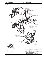
Fig. 2-1-1
(1) Release the lock of the connector
on the left and right.
(2) Pull out the flat cable
Fig. 2-1-2
*1
: Do not the pull out the flat cable or touch the exposed
terminal at the connecting position with your bare
hands as it could cause a defective (1) and (2) shown
in Fig. 2-1-2.
*2
: When the SP circuit board is removed, the crystal filter
and rubber are also removed.
Be careful not to damege and lose them.
1.
Procedure
SP
CIRCUIT
BOARD
CSR
CIRCUIT
BOARD
PC CIRCUIT
BOARD
B
A
B
A
D
C
D
C
CHASSIS (R)
(1) REMOVE
TWO
SCREWS
(2) REMOVE
TWO
SCREWS
(3) REMOVE
TWO
SCREWS
CHASSIS (L)
(4) DISCONNECT
FLAT CABLE
(*1)
(5) REMOVE ONE SCREW
(6) REMOVE THE
PC CIRCUIT
BOARD
(7) REMOVE
ONE
SCREW
(8) REMOVE
THE CSR
CIRCUIT
BOARD
(9) REMOVE TWO
SCREWS
(*2)
(10) REMOVE
TWO
SCREWS
CCD
SENSOR
RUBBER
CRYSTAL
FILTER
LENS
BLOCK
CAMERA
CHASSIS
(11) REMOVE
TWO
SCREWS
(12) REMOVE
ONE
SCREW
(1)
(1)
(2)


