background image

3 - 9

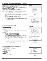
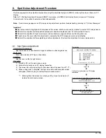
Procedure:

1)

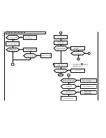
Input 2 to PC on the adjustment menu screen.

2)

The matrix adjustment screen will appear.

3)

Press the D key to minimize the yellow (YEL) level.
Press the U key so the ratio between  yellow (YEL) and blue (BLU) levels
is 1:4.
Press the Ctrl key and hold it down, then press the U and keys so the
ratio between yellow (YEL) and blue (BLU) levels is 1:4.

4)

Press the Enter key: The PC display will switch from the matrix data write
screen to matrix adjustment complete screen.

5)

Press any key to restore the adjustment menu screen.

<< ADJUSTMENT OF BLUE MATRIX >>

ROUGH ADJUSTMENT

FINE ADJUSTMENT

[Crt] + [U]

UP

[Crt] + [D]

DOWN

[ENTER]

SAVE & RETURN TO MENU

[ESC]

QUIT

[U]

UP

[D]

DOWN

Matrix adjustment

Matrix data write

Set the ratio between  yellow (YEL) and blue
(BLU) levels is 1:4.

Matrix adjustment complete

Press Enter key.

Press any key.

<< ADJUSTMENT OF BLUE MATRIX >>

DATA WRITING INTO EEPROM

<< ADJUSTMENT OF BLUE MATRIX >>

ADJUSTMENT FINISHED

PRESS ANY KEY

7.3

White Balance Adjustment 

 [For TYPE S/SE]

Incompleted Phenomenon:

Color of the subject is different from that of the picture.
A white subject is not seen as white.

Equipment/Jig:

C12 light balance filter

Conditions:

Attach a C12 light balance filter to lens.
Set the zoom to wide end, and point at a gray scale chart.

Procedure:

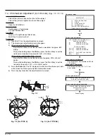
1)

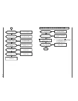
Input 3 to PC on the adjustment menu screen.

2)

Follow the instructions on PC display thereafter.

3)

After the white balance adjustment complete screen appears, press any
key to restore the adjustment menu screen.

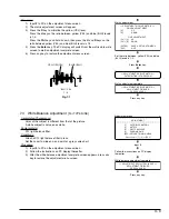
Fig. 7-1

BLUE (BLU)

YELLOW (YEL)

BLU : YEL

1 : 4

***********************************************************

ADJUSTMENT

***********************************************************

[1]

AUTO IRIS CONTROL

[2]

MATRIX

[3]

WHITE BALANCE

[4]

CHROMA GAIN

[ESC] RETURN TO MAIN MENU

Please select [1] - [3] or [ESC]

Adjustment menu

Input 3.

Follow the instructions on PC display
thereafter.

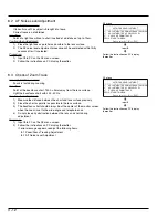
<< ADJUSTMENT OF WHITE BALANCE >>

ADJUSTMENT FINISHED

PRESS ANY KEY

White balance adjustment complete

Press any key.

Содержание VK-K274

Страница 1: ...SERVICE MANUAL SPECIFICATIONS AND PARTS ARE SUBJECT TO CHANGE FOR IMPROVEMENT Digital Media Products Division Tokai COLOR B W VIDEO CAMERA 2001 September TK No 8104E VK S274 S274E VK K274 K274E ...

Страница 2: ...TACHI Service Manual A subscription to or additional copies for HITACHI Service Manual may be obtained at a nominal charge from HITACHI SALES CORPORATION PRODUCT SAFETY NOTICE Cautions Microsoft MS MS DOS Windows and Windows NT are registered trademarks of Microsoft Corporation Pentium and Celeron are registered trademarks of Intel Corporation Manufactured under license from Dolby Laboratories Dol...

Страница 3: ...cation 5 All tolerances other than 5 are indicated in schematic diagrams No indication 1 8W 1 16W for leadless resistors without indication All capacitances other than the above are indicated in schematic diagrams Capacitors Item Value Dielectric strength Indication No indication µF P pF No indication 50V All dielectric strengths other than 50V are indicated in schematic diagrams Item Value Indica...

Страница 4: ... 3 12 8 3 Check of Zoom Trace 3 12 9 Spot Noise Adjustment Procedure 3 13 9 1 Spot noise Adjustment 3 13 10 Error Messages 3 14 10 1 Error massage of Electronic Volume and Camera Adjustment 3 14 10 2 Error massage of Autofocus Adjustment 3 15 10 3 Error massage of Spot Noise Adjustment 3 15 10 4 Troubleshooting of Autofocus 3 16 1 No zoom and focus operation 3 16 2 No focus lens operation 3 18 3 N...

Страница 5: ...ning Frequency VK S274 K274 Horizontal 15 734 kHz Vertical 59 94 Hz VK S274E K274E Horizontal 15 625 kHz Vertical 50 Hz Lens F1 6 to 3 8 4 to 88 mm 22 1 power zoom lens with autofocus Video Signal Output VK S274 S274E Composite Signal 1 0 Vp p VK K274 K274E Y Luminance Signal 1 0 Vp p Minimum Required Illumination VK S274 S274E Standard 1 0 lx DS shutter 0 1 lx VK K274 K274E Standard 0 1 lx DS shu...

Страница 6: ... more 470 TV Line or more VK S274 S274E 1 0 lx VK K274 K274E 0 1 lx Not Provided VK S274 VK S274E VK K274 VK K274E VK S274 ICX278AK L IC1001 VK S274E ICX279AK L IC1001 VK K274 ICX278AL 7 IC1001 VK K274E ICX279AL 7 IC1001 µPD16510GR IC1002 HD49323AF IC1101 HG73C053FE IC1121 MSM51V18165F IC1122 TC7SU04FU IC1173 TC7SHU04FUL IC1174 HD64F2238AFA13 S274 IC1201 X25097V1 2 7 IC1202 RN5VD27AA IC1203 TC7SH1...

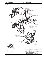
Страница 7: ... is removed the crystal filter and rubber are also removed Be careful not to damege and lose them 1 Procedure SP CIRCUIT BOARD CSR CIRCUIT BOARD PC CIRCUIT BOARD B A B A D C D C CHASSIS R 1 REMOVE TWO SCREWS 2 REMOVE TWO SCREWS 3 REMOVE TWO SCREWS CHASSIS L 4 DISCONNECT FLAT CABLE 1 5 REMOVE ONE SCREW 6 REMOVE THE PC CIRCUIT BOARD 7 REMOVE ONE SCREW 8 REMOVE THE CSR CIRCUIT BOARD 9 REMOVE TWO SCRE...

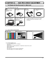
Страница 8: ...meter DVM 3100 K light box DC power supply 9 V 3 A To power of video camera DC power supply 5 V 1 A To power of DSP R jig 1 The adjustment floppy disk is not for sale It will be supplied only when service maintenance contract is concluded DSP R Jig No 7099448 C12 Light Balancing Filter No 7099369 Personal Computer PC Goods on the Market Personal Computer Cable RS 232C 9 or 25 pins Straight Type Go...

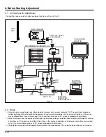
Страница 9: ... using the adjustment program and personal computer PC The adjustment program is subject to change without notice for improvements in functions and operability and the actual instructions on PC screen may be different from those in this manual If so follow the instructions on PC screen to proceed with adjustment 2 Since this chapter uses the device with the highest performance among the models lis...

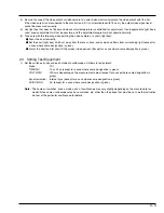
Страница 10: ...from surrounding light except for a case where some designation is given Aim at the chart and let chart fill the screen video period Except for a case where some designation is given 2 3 Setting Test Equipment 1 Set the switches knobs and each mode of oscilloscope as follows for adjustment Probe 10 1 TIME DIV 10 or 20 µs except for a case where some designation is given VOLTS DIV Will vary dependi...

Страница 11: ...he color video camera TYPE S SE CircuitBoards SP Electrical Parts IC1001 IC1101 IC1201 IC1250 1 Other Lens Block Data Initialize Data Initilize 2 Electric Volume CDS Sampling Pulse Camera Adjustment Adjustment Initilizing EEPROM To suppress noise in the CCD sensor output signal and maximize the signal level PC 1 IC1351 Items Purpose Adjustment Auto Iris White Balance 3 Chroma Gain 3 To set the iri...

Страница 12: ...ar on PC display If it is correct input Y to PC If it is incorrect input N and start over from step 8 10 Make sure that the main menu appears on PC display If it does not appear check whether model selection in step 8 is correct 1 If the connection of jig etc is inappropriate or power is not supplied the adjustment program will not start normally 2 For details on how to start MS DOS refer to the i...

Страница 13: ...SE ESC END Please select A F or ESC DATA WRITING START TO SEND DATA Y N 5 1 Data Initialize This procedure initializes the data in EEPROM including the adjustment data Any time you replace the PC circuit board containing EEPROM or EEPROM be sure to perform this procedure Generally this procedure is not necessary after replacing other circuit board components Important After completing this adjustm...

Страница 14: ... If error message appears on PC display during adjustment perform troubleshooting referring to 10 Error Messages Before starting 1 Input B to PC on the main menu screen to display the electronic volume menu screen 1 1 Pressing the Esc key on the adjustment menu screen will restore the main menu screen 6 1 CDS Sampling Pulse Adjustment Incompleted Phenomenon Diagonal beats and horizontal noise occu...

Страница 15: ... screen 2 Input to PC the appropriate adjustment number 1 1 Pressing the Esc key on the adjustment menu screen will restore the main menu screen 7 1 Auto Iris Control Adjustment Incompleted Phenomenon The picture becomes too bright The picture becomes too dark Condition Set the zoom to wide end and point at the light box without chart inserted to fill the screen Procedure 1 Input 1 to PC on the ad...

Страница 16: ...ess any key ADJUSTMENT OF BLUE MATRIX DATA WRITING INTO EEPROM ADJUSTMENT OF BLUE MATRIX ADJUSTMENT FINISHED PRESS ANY KEY 7 3 White Balance Adjustment For TYPE S SE Incompleted Phenomenon Color of the subject is different from that of the picture A white subject is not seen as white Equipment Jig C12 light balance filter Conditions Attach a C12 light balance filter to lens Set the zoom to wide en...

Страница 17: ...Ctrl key press the D or U key to set the red vector to approx 220 5 of burst vector 4 Press the Enter key The PC display will switch from the chroma gain data write screen to chroma gain adjustment complete screen 5 Press any key to restore the adjustment menu screen Chroma gain adjustment ADJUSTMENT 1 AUTO IRIS CONTROL 2 MATRIX 3 WHITE BALANCE 4 CHROMA GAIN ESC RETURN TO MAIN MENU Please select 1...

Страница 18: ...ease select A F or ESC AUTO FOCUS ADJUSTMENT 1 ADJUSTMENT OF ZOOM FOCUS TRACKING 2 ADJUSTMENT OF AF NOISE LEVEL 3 CHECK OF ZOOM TRACE ESC RETURN TO MENU Please select 1 3 or ESC AF menu Input D AUTO FOCUS ADJUSTMENT 1 ADJUSTMENT OF ZOOM FOCUS TRACKING 2 ADJUSTMENT OF AF NOISE LEVEL 3 CHECK OF ZOOM TRACE ESC RETURN TO MENU Please select 1 3 or ESC AF menu Input 1 Follow the instructions on PC displ...

Страница 19: ...mpleted Phenomenon Focus is lost during zooming Condition Point at the backfocus chart 1500 5mm away from the lens surface Light the backfocus chart with 200 400 lx Caution when Adjustment 1 Measure the distance between the chart and lens surface precisely 2 Place the chart as parallel as possible to the lens surface 3 The backfocus chart should always be at the center of the monitor screen when t...

Страница 20: ...abnormal usage conditions or after long term use If spot noise still occurs after this adjustment is complete the CCD image sensor may be defective Perform this adjustment after completing all other adjustments Perform this adjustment in normal video status Main menu MANUAL ADJUSTMENT PROGRAM A DATA INITIALIZE B ELECTRIC VOLUME C ADJUSTMENT D AUTO FOCUS E SPOT NOISE ESC END Please select A F or ES...

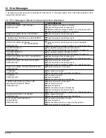
Страница 21: ...djustment program file does not start PRESS ANY KEY Check the adjustment floppy disk and replace it if necessary ERROR OCCURRED ON C DUTY ADJUSTMENT Check the values of the iris drive circuit PRESS ANY KEY Defective soldering damage to pattern etc in the above circuit ERROR OCCURRED ON FDET ADJUSTMENT Supply power again and re adjust PRESS ANY KEY Check the values in the hall amp circuit Defective...

Страница 22: ...eck the conditions of subject If this error message appears even when the adjustment is performed 2 or 3 times the autofocus circuit system is defective Refer to 1 of TROUBLESHOOTING OF AUTOFOCUS TIME OUT ERROR ON ZOOM If this error message appears even when the adjustment is performed 2 or 3 times the autofocus circuit system is defective Refer to 2 of TROUBLESHOOTING OF AUTOFOCUS TIME OUT ERROR ...

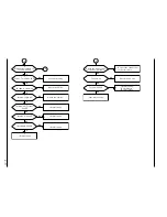
Страница 23: ...t cable TL1346 3V TL1335 PULSE Lens block faulty IC1201 faulty R1215 faulty Q1201 faulty Check the 3V line Correct the connections of the cable NG OK OK OK OK OK NG NG NG NG 2 IC1301 3 PULSE IC1301 4 PULSE Check IC1301 3 IC1201 faulty IC1201 faulty OK NG IC1301 30 PULSE IC1201 faulty 10 4 Troubleshooting of Autofocus This troubleshooting corresponds to 10 2 Error Messages of Autofocus Adjustment I...

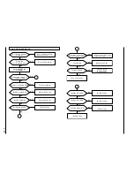
Страница 24: ...lock faulty NG OK NG NG OK NG OK IC1302 12 20 9V NG OK OK IC1302 28 TL1312 PULSE IC1302 3 PULSE IC1201 faulty IC1201 faulty NG NG OK OK IC1302 faulty 4 Check the connections of the lens flat cable TL1346 3V TL1344 PULSE Lens block faulty IC1201 faulty R1214 faulty Q1201 faulty Check the 3V line Correct the connections of the flat cable NG NG NG OK OK OK ...

Страница 25: ...IC1201 faulty IC1201 faulty Check the B line Check the 5V line Lens block faulty See 1 No zoom and focus operation NO NG OK OK NG NG OK NG OK NG OK NG OK OK YES IC1302 30 PULSE IC1201 faulty NG OK 1 OK OK OK NG NG NG Check the connections of the lens flat cable TL1346 3V TL1344 PULSE Lens block faulty IC1201 faulty R1214 faulty Q1201 faulty Check the 3V line Correct the connections of the flat cab...

Страница 26: ...lock faulty Zoom switch faulty See 1 No zoom and focus operation Check the 5V line Check the B line IC1201 faulty OK OK NG 1 1 Check the connections of the lens flat cable TL1346 3V TL1335 PULSE Lens block faulty 2 IC1301 3 PULSE IC1301 4 PULSE IC1301 faulty Correct the connections of the flat cable Check the 3V line IC1201 faulty R1215 faulty Q1201 faulty IC1201 faulty IC1201 faulty NG NG NG NG N...

Страница 27: ...k the 3V line Correct the connections of the flat cable NG OK NG OK NG OK Check the connections of the lens flat cable 1 Set the zoom to the wide angle end Point at the objects from the infinity to close up ends Is there a point at which focus is obtained between the infinity and close up ends Check IC1201 and EEPROM NO OK NG YES TL1345 PULSE 2 3 Initialize the unit and adjust autofocuss Does auto...

Страница 28: ... OK OK OK OK IC1302 30 PULSE IC1201 faulty NG OK 5 SUBJECT IS GREATLY OUT OF FOCUS WHEN ZOOMED NG NO NO OK Check the Zoom switch unit IC1201 49 1 2 1 6V Initialize the unit and adjust autofocus Does autofocus operate normally END IC1201 faulty D1201 C1207 R1205 faulty Zoom switch faulty Note For the item marked perform all the adjustments required when the unit is initialized before adjusting auto...

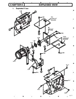
Страница 29: ...2 3 4 A B C D E 1 2 3 4 4 1 CHAPTER 4 EXPLODED VIEW SP CIRCUIT BOARD CSR CIRCUIT BOARD PC CIRCUIT BOARD B A B A 906 906 601 104 102 603 906 907 906 136 908 908 D C 909 913 913 137 D C 138 1 Exploded View ...

Страница 30: ...0 25V C1111 AA00951R CERAMIC CAPACITOR 1 0UF 10 16V C1112 AA00951R CERAMIC CAPACITOR 1 0UF 10 16V C1113 0893193 CERAMIC CHIP 0 01UF 10 25V C1114 0893179 CERAMIC CHIP 0 1UF 10 16V C1115 AA00442R CERAMIC CAPACITOR 10UF 6 3V C1116 AA00441R CHIP CAPACITOR 22UF 20 6 3V C1121 AA00441R CHIP CAPACITOR 22UF 20 6 3V C1122 0893193 CERAMIC CHIP 0 01UF 10 25V C1123 AA01111R CERAMIC CHIP 1UF 6 3V C1124 0893193 ...

Страница 31: ...202 CERAMIC CHIP 330PF 10 50V C1515 0893158 CERAMIC CHIP 56PF 5 50V C1516 0893203 CERAMIC CHIP 390PF 10 50V C1517 0893165 CERAMIC CHIP 180PF 5 50V C1518 0893202 CERAMIC CHIP 330PF 10 50V C1519 0893062 CERAMIC CHIP 1UF 80 20 16V C1520 0206671 ELECTROLYTIC 10UF 10V C1521 AA00381R CERAMIC CHIP 10UF 10 6 3V C1522 0893062 CERAMIC CHIP 1UF 80 20 16V C1523 0206671 ELECTROLYTIC 10UF 10V C1524 AA00441R CHI...

Страница 32: ...HM 5 1 16W R1368 0790064 CHIP RESISTOR 100KOHM 5 1 16W R1370 0790044 CHIP RESISTOR 3 3KOHM 5 1 16W R1371 0790029 CHIP RESISTOR 270 OHM 5 1 16W R1372 0790046 CHIP RESISTOR 4 7KOHM 5 1 16W R1374 0790049 CHIP RESISTOR 8 2KOHM 5 1 16W R1375 0790036 CHIP RESISTOR 820 OHM 5 1 16W R1376 0790047 CHIP RESISTOR 5 6KOHM 5 1 16W R1378 0790047 CHIP RESISTOR 5 6KOHM 5 1 16W R1501 0790052 CHIP RESISTOR 12KOHM 5 ...

Страница 33: ... CA10271R TRANSISTOR 2SB1424 Q1506 5326422 TRANSISTOR 2SC4081 Q1601 1323273 TRANSISTOR DTA143EE Q1602 1323271 TRANSISTOR DTC144EE Q1603 1323279 TRANSISTOR DTC114YE Q1605 1323231 TRANSISTOR 2SB1462 Q1607 5328221 TRANSISTOR 2SC2620 QC Q1609 1323253 TRANSISTOR XP4401 Q1610 1323291 TRANSISTOR 2SC4617 Q1611 1323231 TRANSISTOR 2SB1462 ZD1171 CC10433R DIODE MA3030L TRANSFORMER T1501 BC10261R TRANS COILS ...

Страница 34: ...T 18 Q1152 B 1 0Vp p 0 2V 20 0µs COLOR CHART 19 Q1153 B 550mVp p 0 2V 20 0µs COLOR CHART 16 IC1201 75 3 0Vp p 1V 5 0ms COLOR CHART 17 IC1201 78 3 0Vp p 1V 5 0ms COLOR CHART 11 IC1101 18 4 2Vp p 1V 50 0ns COLOR CHART 12 IC1101 19 4 2Vp p 1V 50 0ns COLOR CHART 7 IC1002 13 3 1Vp p 1V 5 0ms COLOR CHART 8 IC1002 14 3 1Vp p 1V 20 0µs COLOR CHART 5 IC1002 7 3 1Vp p 1V 20 0µs COLOR CHART 14 IC1201 38 3 0V...

Страница 35: ...1 3 3 7 1 15 1 17 0 12 0 10 0 5 0 0 2 0 15 1 15 1 7 0 0 15 0 9 8 10 5 1 3 2 4 8 5 9 10 6 7 To PROCESS PC PG1241 To SWITCHING REGULATOR CSR PG1501 DRIVE PULSE GEN IC1001 ICX278AK TYPE S ICX279AK TYPE SE ICX278AL TYPE K ICX279AL TYPE KE CCD SENSOR C CODE PART NAME QC 2SC2620 QC T C 1SS353 VOLTAGE REC MODE SENSOR SP WAVEFORMS No CCD OUT C Y CCD OUT C1018 1µ ...

Страница 36: ...0 0 0 0 0 0 0 0 0 0 2 0 3 3 3 3 3 3 3 3 3 3 3 3 3 3 3 3 3 0 2 8 0 6 3 3 0 0 3 3 0 3 3 0 3 3 0 3 3 3 3 0 0 0 0 0 0 0 0 0 0 0 0 3 3 3 3 3 3 3 3 0 3 3 3 3 0 3 3 3 3 0 0 0 0 3 3 0 3 3 0 0 0 0 0 0 0 0 3 3 3 3 3 3 3 3 3 3 3 3 3 3 3 0 3 3 3 3 0 0 0 0 0 3 3 3 3 1 6 1 6 0 3 0 3 0 3 0 3 0 3 0 3 0 3 0 3 5 5 0 8 3 8 3 0 0 0 0 0 0 5 3 3 8 3 0 0 0 0 0 5 3 3 8 3 14 7 14 7 5 5 2 1 0 8 2 1 0 8 12 3 14 0 10 0 7 4 9...

Страница 37: ...4 5 4 12 3 14 0 10 0 7 4 10 0 5 0 0 5 0 0 5 0 0 5 0 0 3 3 0 8 0 0 3 3 8 0 0 8 0 0 0 0 2 2 2 1 2 2 2 2 2 1 2 1 2 9 2 2 0 4 2 4 2 2 2 1 4 1 3 2 5 2 2 0 6 2 0 2 0 2 9 2 6 5 0 5 0 3 3 2 0 1 4 2 7 0 1 1 1 7 0 0 0 0 3 3 2 6 VOLTAGE REC MODE WAVEFORMS No To LENS BLOCK To SENSOR SP PG1001 Y C CDS AGC A D CONV HD64 270 BIAS F DET IRIS DRIVE ZOOM MOTOR DRIVE FOCUS MOTOR DRIVE CODE PART NAME AR 2SB1462 BR 2S...

Страница 38: ... 0 8 0 0 5 3 3 0 3 3 0 3 3 0 3 3 0 3 3 0 3 3 0 0 3 3 0 3 3 0 3 3 0 3 3 0 3 3 0 0 0 0 0 0 2 0 2 0 3 3 3 3 3 3 3 3 0 3 3 0 3 3 0 3 3 0 3 3 0 3 3 0 3 3 0 3 3 3 3 0 0 3 3 0 3 3 0 3 3 0 3 3 0 3 3 0 3 3 0 3 3 0 3 3 0 0 0 0 0 0 0 0 0 0 0 3 3 3 3 3 3 3 3 3 3 3 3 3 3 3 3 0 1 0 0 0 0 0 0 0 0 0 0 0 0 3 3 3 3 3 3 3 3 3 3 3 0 2 8 0 6 3 3 0 0 3 3 0 3 3 0 3 3 0 3 3 3 3 0 0 0 0 0 0 0 0 0 0 0 0 3 3 3 3 3 3 3 3 0 3...

Страница 39: ...3 5 0 0 0 5 0 5 0 2 0 0 5 0 3 3 0 5 0 0 0 0 0 0 0 0 0 0 0 0 3 2 0 2 5 0 2 6 4 2 4 2 5 0 5 0 5 0 5 0 0 5 0 0 5 0 3 2 3 3 3 3 3 2 3 2 0 0 0 0 0 0 8 1 0 8 1 0 8 1 8 1 8 0 0 8 0 0 8 2 7 7 7 4 8 2 7 7 7 4 8 2 7 7 7 4 8 2 7 7 7 4 8 2 7 7 7 3 8 0 0 10 8 0 0 7 1 7 1 15 1 OUTPUT IC1604 IDC 7S08 E2 AMP VCO PHASE COMPA LEVEL SHIFT 6dB C1608 0 1 Y C MIX VIDEO AMP 22P TYPE S 12P TYPE SE TYPE S SE TYPE K KE To ...

Страница 40: ...0 A 4C C1361 A 4C C1362 A 4C CP CP1151 B 2C CP1171 A 5A D D1151 B 2C D1171 A 4A D1201 B 5B D1202 B 3B D1351 A 5B IC IC1101 B 1A IC1121 B 2B IC1122 A 2C IC1173 B 5B IC1174 A 3A IC1201 B 4A IC1202 A 3A IC1204 B 3B IC1205 B 3B IC1206 B 4B IC1251 A 3A IC1301 B 4B IC1302 B 5C IC1351 A 5C L L1101 A 2B L1102 B 1A L1103 A 2C L1201 A 3A L1202 A 4C L1301 A 3C L1302 B 4C PG PG1241 A 1B PG1250 A 5A PG1302 B 3...

Страница 41: ... B 3C D1602 B 3A F F1601 B 3C IC IC1501 B 3A IC1601 A 2C IC1602 B 1C IC1603 B 1B IC1604 A 1C L L1501 A 3A L1503 A 2A L1504 A 1A L1505 A 1A L1506 B 2B L1507 B 2B L1601 A 2C L1602 A 1B L1603 A 3C PG PG1501 A 3B PG1601 B 3C Q Q1501 B 2A Q1502 B 1A Q1503 B 1A Q1504 B 1B Q1506 B 2B Q1601 B 1C Q1602 B 1C Q1603 A 1C Q1605 A 3C Q1607 B 2C Q1609 B 2C Q1610 B 2C Q1611 B 3C R R1501 B 2A R1505 B 3A R1509 B 3A...

Страница 42: ...1332 TL1347 PC PROCESS SIDE B PATTERN No JA1936 2 1 2 3 4 5 1 2 3 4 5 A B C A B C PC PROCESS Provided Not Provided DIFFERENCE TABLE Q1153 R1162 R1164 R1165 R1218 R1219 B 2C B 2C B 2C B 2C B 3A B 3A SYMBOL No Parts Location TYPE S TYPE SE TYPE K TYPE KE JUMPER JUMPER JUMPER JUMPER NOTE This table listes the different components marked with asterisks in the circuit board diagrams ...

Страница 43: ...ERN No JA1936 2 A 1 2 3 1 2 3 B C A B C CSR SWITCHING REG SIDE A A 1 2 3 1 2 3 B C A B C CSR SWITCHING REGULATOR DIFFERENCE TABLE NOTE This table listes the different components marked with asterisks in the circuit board diagrams TYPE S TYPE SE TYPE K TYPE KE C1608 C1610 C1617 L1603 Q1605 R1625 R1626 R1627 A 2C A 3C A 3C A 3C A 3C A 3C A 3C A 3C SYMBOL No Parts Location Provided Not Provided ...

Страница 44: ...D M M M DRIVE ZOOM MOTOR IRIS MOTOR HALL DEVICE FOCUS MOTOR Q1201 LED DRIVE DECORD BIAS F DET IRIS DRIVE Q1352 Q1353 IC1351 F DET IRIS DRIVE IC1301 ZOOM MOTOR DRIVE 30 28 3 15 13 19 17 DRIVE DRIVE DECORD IC1302 FOCUS MOTOR DRIVE Q1351 BIAS DRIVE 43 52 69 44 26 10 8 34 27 9 36 41 39 33 30 ZOOM LED FCUS LED FUS SENS ZOM SENS RDCW RDCK RD RESET ZDCW ZD OEB ZDCK RD OEB ZD RESET HAL ADJ0 HALL G F DET H...

Страница 45: ...OM MOTOR DRIVE 27 O Hi RD RESET Resets IC1302 FOCUS MOTOR DRIVE 28 O Pulse IRIS PWM Iris motor drive output 29 LD JIG Not used Open 30 O Pulse ZOOM LED Output pulses to drive the ZOOM LED in the lens block via Q1201 LED DRIVE 31 TXD2 Not used 32 RXD2 33 O Pulse FCUS LED Output pulses to drive the FOCUS LED in the lens block via Q1201 LED DRIVE 34 O Hi Lo ZDCW Issues a command which determines with...

Страница 46: ...DET IRIS DRIVE 70 Not used Open 71 72 I Pulse HD Inputs horizontal sync from IC1121 CAMERA DSP 73 SHUT CTL Not used Open 74 STROBE 75 I Pulse FP Inputs field discrimination pulse from IC1121 CAMERA DSP 76 O Pulse SD 232C Used for initial settings and adjustment For data communications with personal 77 I Pulse RD 232C computer 78 I Pulse EP3 Receives pulses which discriminate the iris detection are...

Страница 47: ...Copyright Hitachi Ltd 2001 All rights reserved Printed in Japan I Digital Media Products Division Tokai TK No 8104E VK S274 S274E VK K274 K274E VK S274 S274E K274 K274E VK S274 S274E K274 K274E ...

Отзывы: