background image


8.

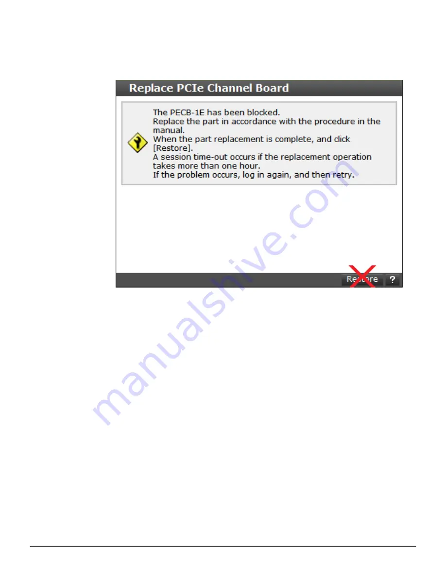
Check that the PCIe switch board is blocked and becomes ready for

replacing. Do not click 

Restore

 at this time.


Replacing a PCIe switch board

Procedure

1.

Loosen the blue screws on the PCIe switch board and open the lever.

2.

If the lever opens completely, the PCIe switch board is pulled out.

3.

Hold the body of the PCIe switch board with both hands and remove it.
 

288

Replacing a PCIe switch board

Service Guide for VSP Gx00 and VSP Fx00 Models

Содержание Virtual Storage Platform F400

Страница 1: ...Service Guide Hitachi Virtual Storage Platform G200 G400 G600 G800 Hitachi Virtual Storage Platform F400 F600 F800 FE 94HM8027 06 March 2017 ...

Страница 2: ...bject to U S export control laws including the U S Export Administration Act and its associated regulations and may be subject to export or import regulations in other countries Reader agrees to comply strictly with all such regulations and acknowledges that Reader has the responsibility to obtain licenses to export re export or import the Document and any Compliant Products Hitachi is a registere...

Страница 3: ...reproduce the above copyright notice this list of conditions and the following disclaimer in the documentation and or other materials provided with the distribution Neither the name of the Intel Corporation nor the names of its contributors might be used to endorse or promote products derived from this software without specific prior written permission THIS SOFTWARE IS PROVIDED BY THE COPYRIGHT HO...

Страница 4: ...4 Service Guide for VSP Gx00 and VSP Fx00 Models ...

Страница 5: ...hock 17 For fire 17 Audience and qualifications 18 Product version 18 Release notes 18 Changes made in this revision 18 Document conventions 19 Conventions for storage capacity values 20 Accessing product documentation 20 Getting help 21 Comments 21 1 Verifying component failures 23 Replaceable parts 24 Identifying hardware faults 24 2 Hardware description 31 Storage system controllers 32 CBSS con...

Страница 6: ...s 54 CBSS CBSL AC power supply unit LEDs and connectors 55 CBSSD CBSLD DC power supply unit LEDs and connectors 55 CBLM power supply unit LEDs and connectorsCBLH power supply unit LEDs and connectors 56 Storage system drive trays 57 Small form factor SFF drive tray 57 SFF with front panel bezel 57 SFF front panel without bezel 58 SFF rear panel 59 Large form factor LFF drive tray 59 LFF with front...

Страница 7: ...CBSLAttaching the front bezel to an FMDAttaching a front bezel to an SFF LFF or FMD 90 Removing the front bezel from a DBS or DBL drive tray 90 Removing the front bezel from a CBLM CBLH controller 91 Attaching the front bezel to a CBLM CBLH controller 92 Attaching the front bezel to a dense intermix drive tray 93 Removing the front bezel from a dense intermix drive tray 94 Removing cables 94 Loggi...

Страница 8: ...nnections on a host port expansion chassis 155 Checking power cable connections on a host port expansion chassis 157 8 Replacing a controller 161 Blocking the controller 162 Replacing a controller for a CBSS or CBSL controller 164 Removing the controller 164 Removing and installing the fan 165 Removing and installing cache memory 166 Removing and installing a front end module 168 Removing and inst...

Страница 9: ...dule 218 Replacing an SFP for a NAS module 219 Restoring the SFP for a NAS module 221 13 Replacing a back end module 223 Blocking a back end module 224 Adding or replacing the back end module 226 Restoring a DKB 228 14 Replacing an ENC 229 Blocking an ENC 230 Replacing the ENC for SFF and LFF drive trays 232 Replacing the ENC for a FMD drive tray 233 Restoring an ENC 234 15 Replacing a SAS cable 2...

Страница 10: ...itch board 289 21 Replacing a PCIe cable connector 291 Blocking a PCIe cable connector 292 Replacing a PCIe cable connector 294 Restoring a PCIe cable connector 295 22 Replacing a PCIe cable 297 Blocking a PCIe cable 298 Replacing the PCIe cable 300 Restoring a PCIe module 301 23 Replacing a NAS module 303 Blocking a NAS module 304 Replacing the NAS module 306 Restoring a NAS module 308 24 General...

Страница 11: ...aintenance Utility window fails or is blank 341 Forcing browser refreshes of the Maintenance Utility window 341 Maintenance Utility window freezes 341 Releasing the system lock 341 Update Firmware window cannot be displayed 342 Duplicate maintenance utility windows appear in Internet Explorer 342 Duplicate maintenance utility windows appear in Google Chrome 342 Request to download a file during fi...

Страница 12: ...drive tray 402 CBSS CBSL CBSSD CBSLD controller 403 CBLM controller CBLH controller 404 Drive for a flash module drive tray DKC F710I 1R6FM DKC F710I 3R2FM 404 Drive for a flash module drive tray DKC F810I 1R6FN DKC F810I 3R2FN DKC F810I 6R4FN 406 Dense intermix drive tray power supply 407 CMA used to secure dense intermix drive tray 408 Battery 409 Host port expansion chassis 409 PCIe switch boar...

Страница 13: ...e Platform F400 F600 F800 Safety and environmental notices General safety guidelines Audience and qualifications Product version Release notes Changes made in this revision Document conventions Conventions for storage capacity values Accessing product documentation Getting help Comments Preface 13 Service Guide for VSP Gx00 and VSP Fx00 Models ...

Страница 14: ...opment Kit website http sourceforge net apps mediawiki tianocore index php title UDK2010 2004 Intel Corporation All rights reserved Redistribution and use in source and binary forms with or without modification are permitted provided that the following conditions are met Redistributions of source code must retain the above copyright notice this list of conditions and the following disclaimer Redis...

Страница 15: ...em according to the information in this manual Read the following safety guidelines carefully and follow them when you conduct maintenance of the machine Do not use materials that are outside the specifications for the storage system Use the spare parts consumables and materials for maintenance that are specified in this manual otherwise personal injury system damage and degradation in system qual...

Страница 16: ...torage system Do not leave any tools or foreign material in the storage system Working when the storage system is in operation Observe the following safety measures when working on a storage system that is in operation When you perform maintenance do not touch live electric parts to prevent an electric shock Do not touch heat sinks immediately after a board is removed because the heat sinks can be...

Страница 17: ... working with the storage system while it is in operation For electric shock Before performing maintenance clear away any potential electric hazards in the maintenance area such as insufficient grounding loose electrical cables or a wet floor Before performing maintenance locate the emergency off switches and know how to operate them Unless instructed remove all power sources to the storage system...

Страница 18: ...nt revision applies to Hitachi Virtual Storage Platform G200 G400 G600 G800 and Hitachi Virtual Storage Platform F400 F600 F800 firmware 83 04 2x or later Release notes Read the release notes before installing and using this product They may contain requirements or restrictions that are not fully described in this document or updates or corrections to this document Release notes are available on H...

Страница 19: ...om the surrounding text or from other variables Example Status report name file version csv Variables in headings square brackets Indicates optional values Example a b indicates that you can choose a b or nothing braces Indicates required or expected values Example a b indicates that you must choose either a or b vertical bar Indicates that you have a choice between two or more options or argument...

Страница 20: ... capacity values for example logical device capacity cache memory capacity are calculated based on the following values Logical capacity unit Value 1 block 512 bytes 1 cylinder Mainframe 870 KB Open systems OPEN V 960 KB Others 720 KB 1 KB 1 024 210 bytes 1 MB 1 024 KB or 1 0242 bytes 1 GB 1 024 MB or 1 0243 bytes 1 TB 1 024 GB or 1 0244 bytes 1 PB 1 024 TB or 1 0245 bytes 1 EB 1 024 PB or 1 0246 ...

Страница 21: ... independent software vendors employees and prospects It is the destination to get answers discover insights and make connections Join the conversation today Go to community hds com register and complete your profile Comments Please send us your comments on this document to doc comments hds com Include the document title and number including the revision level for example 07 and refer to specific ...

Страница 22: ...22 Preface Service Guide for VSP Gx00 and VSP Fx00 Models ...

Страница 23: ... failures This chapter describes how to use the maintenance utility to confirm component failures Replaceable parts Identifying hardware faults Verifying component failures 23 Service Guide for VSP Gx00 and VSP Fx00 Models ...

Страница 24: ...L Backup module BKMF for CBLM or CBLH Identifying hardware faults There are several ways the storage system can alert you to failures When notified about an error by email or the Simple Management Network Protocol SMNP When a failure is indicated by storage system LED for example WARNING or ALARM LED goes on or READY LED does not go on To identify a failed part and recover the storage system Proce...

Страница 25: ...4 In the left pane of the Maintenance Utility window circled in the figure below check the Status of the storage system Verifying component failures 25 Service Guide for VSP Gx00 and VSP Fx00 Models ...

Страница 26: ...ning status No Yes Ready All parts have a normal status No Yes Power on in progress Power on is in progress Power off in progress Power off is in progress Unknown The storage system is in an unknown state prior to power on 5 At the top right of the Maintenance Utility window click Alert 26 Verifying component failures Service Guide for VSP Gx00 and VSP Fx00 Models ...

Страница 27: ...e window switches to the Alerts tab 6 Click the Alert ID The Alert Detail window shows the failed part that must be replaced Verifying component failures 27 Service Guide for VSP Gx00 and VSP Fx00 Models ...

Страница 28: ...odes Reference code Recovery action Reference aff20x Tighten the Cache Flash Memory CFM screw if necessary Replacing cache flash memory on page 251 af400x Tighten the backup module BKM BKMF screw if necessary Replacing a backup module on page 269 af200x Check power supply DKCPS connections Replacing a power supply on page 141 af210x Check the connection of the power cables on the power supply DKCP...

Страница 29: ...expansion chassis on page 157 af4b0x Check the connection of the CHBBPS power cables to the CHBB power supply unit Checking power cable connections on a host port expansion chassis on page 157 af4cxx Check that the screw is secure on the CHBBFAN fan Checking the screw on a host port expansion chassis fan on page 137 Reference codes other than those above Contact the HDS Support Portal at https sup...

Страница 30: ...In this example Drive slot location of the drive in the drive tray DB number of the drive tray 30 Verifying component failures Service Guide for VSP Gx00 and VSP Fx00 Models ...

Страница 31: ...orage system controllers Virtual Storage Platform G200 Virtual Storage Platform G400 G600 Virtual Storage Platform G800 Virtual Storage Platform F400 F600 Virtual Storage Platform F800 Controller LEDs and interfaces Storage system drive trays Host port expansion chassis NAS Module Ports and LEDs Hitachi Virtual Storage Platform Service processor server Hardware description 31 Service Guide for VSP...

Страница 32: ...h front panel bezel The following table describes the definitions of the CBSS controller front panel bezel LEDs Number Item Description 1 POWER LED Green Storage system is powered on Amber Storage system is receiving power 2 READY LED Green Normal operation 3 WARNING LED Off Normal operation Amber Component requires maintenance Blink Failure requires maintenance Note When System Option Mode 1097 i...

Страница 33: ...urn off These LEDs return to their on state after the storage system recovers from the controller replacement CBSS front panel without bezel The following table describes the definitions of the CBSS controller front panel LEDs Number Item Description 1 ACT LED Green Normal operation Blink green Drive is being accessed 2 ALM LED Red Drive stopped due to a failure and can be replaced 3 POWER READY W...

Страница 34: ...el LEDs Number Item Description 1 Controllers Controller 1 left and Controller 2 right 2 Front end module N A 3 CTL ALM LED Red Controller can be removed Blink red Failure with the power supply unit of the controller Amber LAN reset switch was pressed 4 BACKUP STTS LED Green Power restoration in progress following power outage Fast blink green Restoring Slow blink green Restoring or sequential shu...

Страница 35: ...up module is charging or discharging Red Backup module can be removed Blink red Backup module can be removed Blink red one time Battery failure Off battery is not installed failure occurred or firmware is being upgraded 13 SAS port N A 14 Port LED Blue Port link is established 15 Power supply unit N A CBSL controller The CBSL controller includes specific functional LEDs located on the front and re...

Страница 36: ...x 4100xx and 410100 LED might turn off during user maintenance 4 ALARM LED Off Normal operation Red Processor failure system might be down Go to the Customer Contact Us page at https support hds com en_us contact us html 5 POWER ON OFF main switch Powers the storage system 6 Lock Locks and unlocks the front panel bezel by using the supplied key Note Removing a controller can cause the POWER READY ...

Страница 37: ...set to ON the WARNING LED does not blink even if the following failure service information messages SIM are issued 452xxx 462xxx 3077xx 4100xx and 410100 4 POWER ON OFF main switch Powers the storage system 5 Large form factor drives The twelve 3 5 inch large form factor drives are positioned horizontally The slots are organized in the following order 8 9 10 11 4 5 6 7 0 1 2 3 CBSL rear panel The ...

Страница 38: ... green Restoring Slow blink green Restoring or sequential shutdown in progress 5 CTL WARN LED Amber blink one time Failure with fan 0 Amber blink two times Failure with fan 1 6 Cache flash memory N A 7 LAN RST switch Use only when instructed by customer support 8 LAN port Maintenance LAN port left and user LAN port right 9 Uninterruptible power supply UPS port N A 10 ALARM LED for cache flash memo...

Страница 39: ...lled failure occurred or firmware is being upgraded 13 SAS port N A 14 Port LED Blue Port link is established 15 Power supply unit N A CBLM controller The CBLM controller includes specific functional LEDs located on the front and rear of controller and power supplies to provide its operating status CBLMCBLH with front panel bezel The following table describes the definitions of the CBLMCBLH contro...

Страница 40: ... 4 ALARM LED Off Normal operation Red Processor failure system might be down Go to the Customer Contact Us page at https support hds com en_us contact us html 5 POWER ON OFF main switch Powers the storage system 6 Lock Locks and unlocks the front panel bezel by using the supplied key Note Removing a controller can cause the POWER READY WARNING and ALARM LEDs on the front panel to turn off These LE...

Страница 41: ... top 4 Backup module N A 5 BACKUP LED Green Power restoration in progress following power outage Fast blink green Restoring Slow blink green Restoring or sequential shutdown in progress 6 Cache flash memory N A 7 ALM LED for cache flash memory Red Cache flash memory can be removed 8 CTL ALM LED Red Controller can be removed Blink red Failure with the power supply unit of the controller Amber LAN r...

Страница 42: ...mes Both batteries failed or preventive maintenance replacement of batteries can run Off Battery is not mounted battery mounting failure occurred or firmware is being upgraded Off is normal status for configurations without batteries for example BKMF 10 and BKMF 20 CBLMCBLH rear panel The following table describes the definitions of the CBLMCBLH controller rear panel LEDs 42 Hardware description S...

Страница 43: ...blade 5 Power supply unit CBLH controller The CBLH controller includes specific functional LEDs located on the front and rear of controller and power supplies to provide its operating status CBLH with front panel bezel The following table describes the definitions of the CBLH controller front panel bezel LEDs Hardware description 43 Service Guide for VSP Gx00 and VSP Fx00 Models ...

Страница 44: ...D does not blink even if the following failure information issues SIM Failure information SIM 452xxx 462xxx 3077xy 4100xx and 410100 LED might go OFF during user maintenance 4 Alarm Off Normal operation Red Processor failure system may be down Go to the Customer Contact Us page at https support hds com en_us contact us html 5 Power ON OFF Powers the storage system 6 Lock Locks and unlocks the fron...

Страница 45: ...e storage system 2 POWER READY WARNING and ALARM LEDs See the previous table 3 Controllers Controller 1 bottom and Controller 2 top 4 Backup module N A 5 BACKUP LED Green Power restoration in progress following power outage Fast blink green Restoring Slow blink green Restoring or sequential shutdown in progress 6 Cache flash memory N A 7 ALM LED for cache flash memory Red Cache flash memory can be...

Страница 46: ...d two times Backup battery failure Blink red three times Both batteries failed or preventive maintenance replacement of batteries can run Off Battery is not mounted battery mounting failure occurred or firmware is being upgraded Off is normal status for configurations without batteries for example BKMF 10 and BKMF 20 CBLH rear panel The following table describes the definitions of the CBLH control...

Страница 47: ...0 Virtual Storage Platform G400 G600 Virtual Storage Platform G800 Virtual Storage Platform F400 F600 Virtual Storage Platform F800 Controller LEDs and interfaces The controllers are equipped with interfaces for connecting powering configuring and managing the storage system The component LEDs display the operating status of the storage system Hardware description 47 Service Guide for VSP Gx00 and...

Страница 48: ... Front end module is in the power on state Red Front end module can be removed safely 2 PORT LED Red Small form factor pluggable can be removed Blue Normal link status Blink blue Front end module is in communication status 3 iSCSI connectors Connect to Ethernet LAN cables 10 Gbps iSCSI board LEDs and connectors copper 48 Hardware description Service Guide for VSP Gx00 and VSP Fx00 Models ...

Страница 49: ...reen 10 Gbps link Off No link connection 3 PORT LED Green Link connection is established Blinking Communication is in progress Off No link connection or not ready to communicate 4 iSCSI connectors Connect to Ethernet LAN cables 8 Gbps 16 Gbps or 32 Gbps Fibre Channel 4 port board LEDs and connectors Hardware description 49 Service Guide for VSP Gx00 and VSP Fx00 Models ...

Страница 50: ...us at 8 Gbps Green Normal link status at 2 Gbps or 4 Gbps Table 2 32 Gbps 16 Gbps Fibre Channel Number Item Description 1 Fibre Channel connectors Connect to Fibre Channel cables 2 STATUS LED Green Front end module is in power on state Red Front end module can be removed safely 3 PORT LED Red Small form factor pluggable can be removed Blue Normal link status at 16 Gbps 16 Gbps Blue Normal link sta...

Страница 51: ... 3 Port 4 CHB 1A 1A 3A 5A 7A CHB 1B 1B 3B 5B 7B CHB 1C 1C 3C 5C 7C CHB 1D 1D 3D 5D 7D CHB 1E 1E 3E 5E 7E CHB 1F 1F 3F 5F 7F CHB 1G 1G 3G 5G 7G CHB 1H 1H 3H 5H 7H CHB 2A 2A 4A 6A 8A CHB 2B 2B 4B 6B 8B CHB 2C 2C 4C 6C 8C CHB 2D 2D 4D 6D 8D CHB 2E 2E 4E 6E 8E CHB 2F 2F 4F 6F 8F CHB 2G 2G 4G 6G 8G CHB 2H 2H 4H 6H 8H 16 Gbps Fibre Channel 2 port board LEDs and connectors Hardware description 51 Service...

Страница 52: ...4 Gbps or 8 Gbps 3 Fibre Channel connectors Connect to Fibre Channel cables Port assignments CHB number 16 Gbps Fibre Channel Ports left to right Port 1 Port 2 CHB 1A 1A 3A CHB 1B 1B 3B CHB 1C 1C 3C CHB 1D 1D 3D CHB 1E 1E 3E CHB 1F 1F 3F CHB 1G 1G 3G CHB 1H 1H 3H CHB 2A 2A 4A CHB 2B 2B 4B CHB 2C 2C 4C CHB 2D 2D 4D CHB 2E 2E 4E CHB 2F 2F 4F CHB 2G 2G 4G CHB 2H 2H 4H PCIe module 52 Hardware descript...

Страница 53: ...d Off PCIe module can be removed safely 2 Link Green PCIe is Gen 3 8 Gbps and is linked up normally Off PCIe is not linked up PCIe cable might not be connected If a PCIe cable is connected it can be removed safely LAN blade LEDs and connectors Hardware description 53 Service Guide for VSP Gx00 and VSP Fx00 Models ...

Страница 54: ...vice personnel 5 LAN ALARM LED Red LAN blade can be removed 6 Uninterruptible power supply UPS port N A Back end module LEDs and connectors The back end module LEDs display the operating status of the module Number Item Description 1 PATH 1 connector Connects to a drive tray 2 PORT LED Blue Normal link status 54 Hardware description Service Guide for VSP Gx00 and VSP Fx00 Models ...

Страница 55: ...cribes the definitions of the CBSS and CBSL AC power supply unit LEDs and connectors Number Item Description 1 Receptacle Connects to the power cable provided with the storage system 2 AC IN LED Blue AC input is normal 3 ALM RDY LED Red Power supply unit can be replaced Green Normal operation CBSSD CBSLD DC power supply unit LEDs and connectors The following table describes the definitions of the ...

Страница 56: ...rmal CBLM power supply unit LEDs and connectorsCBLH power supply unit LEDs and connectors The following table lists the definitions of the CBLMCBLH power supply unit LEDs and connectors Number Item Description 1 ALM RDY LED Red Power supply unit can be replaced 56 Hardware description Service Guide for VSP Gx00 and VSP Fx00 Models ...

Страница 57: ...MD DC2 flash storage devices To deliver consistent low latency host response times and highest IOP performance across all host connection ports no HDDs are included or permitted to be configured as part of these configurations Small form factor SFF drive tray SFF with front panel bezel Number Item Description 1 POWER LED Green Drive tray is powered on 2 READY LED Green Drive tray is operational 3 ...

Страница 58: ...ped due to a failure and can be replaced 3 POWER READY and LOCATE LEDs Green Drive tray is powered on Green Drive tray is operational Amber Indicates the location of the chassis Can be turned on or turned off by the maintenance utility 4 Small form factor drives The twenty four 2 5 inch small form factor drives are positioned vertically The slots are organized from 0 to 23 58 Hardware description ...

Страница 59: ...Connects to a controller or drive tray 7 PATH OUT LED Blue OUT side port is linked up 8 PATH OUT connector Connects to a drive tray 9 Console This port is reserved 10 Power supply unit N A 11 Receptacle Connects to the power cable provided with the storage system 12 AC IN LED Green Normal operation 13 ALM LED Red Power supply unit can be replaced 14 RDY LED Green Normal operation Large form factor...

Страница 60: ...chassis Can be turned on or turned off by the maintenance utility 4 Lock Locks and unlocks the front panel bezel by using the supplied key LFF front panel without bezel Number Item Description 1 POWER READY and LOCATE LEDs Green Drive tray is powered on Green Drive tray is operational Amber 60 Hardware description Service Guide for VSP Gx00 and VSP Fx00 Models ...

Страница 61: ...5 inch large form factor drives are positioned horizontally The slots are organized in the following order 8 9 10 11 4 5 6 7 0 1 2 3 LFF rear panel Number Item Description 1 ENC N A 2 POWER LED Green ENC is in the power on state 3 LOCATE LED Amber Indicates the location of the chassis Can be turned on or turned off by the maintenance utility 4 ALARM LED Red ENC can be replaced 5 PATH IN LED Blue I...

Страница 62: ...n Normal operation 13 ALM LED Red Power supply unit can be replaced 14 RDY LED Green Normal operation Flash module drive FMD tray FMD with front panel bezel Number Item Description 1 POWER LED Green Drive tray is powered on 2 READY LED Green Drive tray is operational 3 LOCATE LED Amber Indicates the location of the chassis Can be turned on or turned off by the maintenance utility 4 Lock Locks and ...

Страница 63: ...lt in capacitor is charged If the storage system is turned on the LED stops blinking when the capacitor is finished charging approximately two minutes Note ACT indicator is only printed on some types of FMDs ALM LED Red Drive stopped due to a failure and can be replaced Note ACT indicator is only printed on some types of FMDs 3 POWER READY and LOCATE LEDs Green Drive tray is powered on Hardware de...

Страница 64: ... organized the following way 9 10 11 6 7 8 3 4 5 0 1 2 FMD rear panel Number Item Description 1 ENC N A 2 POWER LED Green ENC is in the power on state 3 LOCATE LED Amber Indicates the location of the chassis Can be turned on or turned off by the maintenance utility 4 ALARM LED Red ENC can be replaced 5 PATH IN LED Blue IN side port is linked up 64 Hardware description Service Guide for VSP Gx00 an...

Страница 65: ...N LED ALM REPLACE LED Green Power supply unit is operating normally Green Power supply unit is operating normally Red Power supply unit can be replaced Dense intermix drive tray Dense intermix drive tray with front panel bezel Number Item Description 1 POWER LED Green Drive tray is powered on 2 READY LED Green Drive tray is operational 3 LOCATE LED Amber Indicates the location of the chassis Can b...

Страница 66: ... green Drive is being accessed 2 ALM LED Red Drive stopped due to a failure and can be replaced Note At the rear of the drive tray the drives are organized from left to right On the left side of the preceding figure the rear of the drive tray is at the top Rear of drive tray 48 59 36 47 24 35 12 23 Front of drive tray 00 11 66 Hardware description Service Guide for VSP Gx00 and VSP Fx00 Models ...

Страница 67: ...system 6 ENC N A 7 PATH OUT LED Blue OUT side port is linked up 8 PATH OUT connector Connect to a drive tray 9 PATH IN LED Blue IN side port is linked up 10 PATH IN connector Connects to a controller or drive tray 11 Console This port is reserved 12 ALARM LED Red ENC can be replaced 13 LOCATE LED Amber Indicates the location of the chassis Can be turned on or turned off by the maintenance utility ...

Страница 68: ...er Item Description 1 RDY LED Green Normal operation 2 AC IN LED Green AC input is operating normally 3 ALM LED Red Power supply unit can be replaced SFF and LFF DC power supply unit LEDs and connectors Both SFF and LFF drive trays are equipped with DC power supply units The DC power supply units include LEDs to display its operating status Number Item Description 1 RDY LED Green Normal operation ...

Страница 69: ...pansion chassis Host port expansion chassis front panel bezel LEDs Number Item Description 1 POWER LED Green Host port expansion is turned on Amber PCIe module is turned on Off PCIe module is turned off 2 Safety lock Lock or unlock the front bezel PCIe switchboard Hardware description 69 Service Guide for VSP Gx00 and VSP Fx00 Models ...

Страница 70: ...Ie switchboard can be replaced safely Off PCIe switchboard is powered off Host port expansion chassis fan Number Item Description 1 ALM LED Red Fan failure has occurred Off Normal operation PCIe cable connector 70 Hardware description Service Guide for VSP Gx00 and VSP Fx00 Models ...

Страница 71: ... is not linked up PCIe cable might not be connected If a cable is connected it can be removed safely 3 InAct Basic LED Amber Basic PCIe status changed from link up to link down and cables Cables can be removed safely Off Basic PCIe is normal or not set 4 Link Option LED Green Option PCIe Gen 3 0 8 Gbps is linked up normally Off Option PCIe is not linked up PCIe cable might not be Hardware descript...

Страница 72: ...down and cables Cables can be removed safely Off Option PCIe is normal or not set Host port expansion chassis power supply Number Item Description 1 ALM RDY LED Red Host port expansion chassis power supply can be replaced safely Green Normal operation 2 AC IN LED Blue AC input is normal 72 Hardware description Service Guide for VSP Gx00 and VSP Fx00 Models ...

Страница 73: ...4 Link LED Blue Displays link status 5 Fail LED Red A failure has occured Hitachi Virtual Storage Platform Service processor server The VSP Gx00 models include a separate dedicated 1U service processor SVP to host an element manager Storage Navigator The SVP model number 3919435 P operates independently from the CPU of the storage system and operating system and provides out of band configuration ...

Страница 74: ...ware ESXi Linux KVM Note This product is also designed for IT power distribution systems with phase to phase voltage The SVP provides four RJ 45 ports Two ports connect to the storage system controllers one port for each controller One port connects to the IP network of the user One port connects to a user supplied management console PC Three of the four RJ 45 ports which connect to the controller...

Страница 75: ...irus software that has been tested and approved by Hitachi SVP front panel The front panel of the physical SVP is equipped with LEDs a reset button and a power button Number Description 1 LEDs From left to right the LEDs are BMC Heartbeat LAN card 2 LAN card 1 Hard drive System standby power 2 Reset button 3 Power button Applies power to or removes power from the SVP SVP rear panel The only ports ...

Страница 76: ... the management console PC and the user LAN port on each storage system controller Note After the Initial Startup Wizard is run the SVP can be used in non bridge mode In this mode the cables can be removed from SVP ports LAN3 and LAN4 and attached to switches For more information contact customer support 76 Hardware description Service Guide for VSP Gx00 and VSP Fx00 Models ...

Страница 77: ... on and power off work procedures Safety considerations Guidelines for replacing a component Guidelines to follow after replacing a component Using the maintenance utility Replacement parts Attaching and removing the front panel bezel Removing cables Logging on to NAS Manager EVS migration before servicing nodes EVS migration after servicing nodes Checking recovery after replacing components Repla...

Страница 78: ...t Handle any card FRU only by its edges and avoid touching the components or circuitry Do not slide a FRU over any surface Limit body movement which builds up static electricity during the removal and replacement of a FRU To avoid electric shock when performing a hot replacement of a part do not wear metallic accessories or a watch and avoid touching live parts of the storage system with a screwdr...

Страница 79: ...bles supplied with this product Do not use power cables from other products Otherwise unexpected failures or accidents can occur If you encounter unusual odors heat generation or smoke emission shut off power to the equipment and inform the appropriate personnel Leaving such conditions unattended can cause electric shock or fire Keep the area clean and dust free when replacing components Do not bl...

Страница 80: ... off due to an abnormal rise in temperature If a fan on the controller fails at the same time when another component fails replace the fan first and then replace the other failed component Otherwise the system might turn off due to an abnormal rise in temperature Insert replacement parts quickly Otherwise the recovery might fail If only the power main switch is off the power is provided by the bas...

Страница 81: ...rt Maintenance Utility Click in the window to see the help menu for the description of the Maintenance Utility To display the help the settings for enlarging and reducing the display might not be reflected in the help window depending on the type or version of your browser Starting from Hitachi Command Suite Procedure 1 Start Hitachi Command Suite 2 In the Hitachi Command Suite main window click t...

Страница 82: ... web browser from the console PC connected to the SVP and then start Device Manager Storage Navigator 2 Enter the following URL in the address field of your browser and then press Enter http IP address of SVP module sn2 0 index do 3 In the Storage Device List window click the picture of the registered storage system 4 Log in to Device Manager Storage Navigator 5 On the Maintenance Utility menu cli...

Страница 83: ...e Controller board 1 of VSP G200 Cache Memory replacement installation for CTL1 Cache memory installed on controller 1 FAN replacement for CTL1 Fan installed in controller 1 VSP G200 Controller board CTL replacement for CTL2 Controller 2 LAN blade installed on controller 2 VSP G400 G600 or VSP F400 F600 Controller board CTL replacement for CTL2 Controller 2 LAN blade installed on controller 2 VSP ...

Страница 84: ...2785 A DKC F810I 300KCM Yes Yes 300 GB 15 kmin 1 6 Gbps SAS SFF 5552785 P DKC F810I 300KCMC Yes Yes 400 GB MLC 12 Gbps SFF flash drive 5559016 A DKC F810I 400MEM Yes Yes 400 GB MLC 12 Gbps LFF flash drive 5559086 A DKC F810I 400M8M Yes Yes 600 GB 10 kmin 1 6 Gbps SAS SFF contains BNST 5552786 A DKC F810I 600JCM Yes Yes 600 GB 10 kmin 1 6 Gbps SAS SFF 5552786 P DKC F810I 600JCMC Yes Yes 600 GB 15 k...

Страница 85: ...A DKC F810I 6R0H9M Yes Yes 6 TB 7200min 1 12 Gbps SAS 7 2K LFF 5560116 A DKC F810I 6R0HLM Yes Yes 10 TB 7 2K rpm LFF Disk Drive 5562395 A DKC F810I 10RH9M Yes Yes 10 TB 7 2K rpm LFF Disk Drive for DB60 5562396 A DKC F810I 10RHLM Yes Yes 1 75 TB 12 Gbps LFF flash module drive DC2 3286696 A DKC F810I 1R6FN Yes Yes 3 5 TB 12 Gbps LFF flash module drive DC2 3286697 A DKC F810I 3R2FN Yes Yes 7 TB 12 Gb...

Страница 86: ...90733 A DW F800 CTLS Yes Yes CBSS and CBSL encryption 3290733 B DW F800 CTLSE Yes Yes CBLM 3289039 A DW F800 CTLM Yes Yes CBLH 3289038 A DW F800 CTLH Yes Yes Cache memory 8 GB 3290718 A DKC F810I CM8G Yes Yes 16 GB 5552764 A DKC F810I CM16G Yes Yes 32 GB 5552765 A DKC F810I CM32G Yes Yes Front end modules 10 Gbps SFP iSCSI optical 3289048 A DW F800 2HS10S Yes Yes 10 Gbps iSCSI copper 3289049 A DW ...

Страница 87: ...LM 3289045 A DW F800 BS12G Yes Yes CBLM Encryption 1 3289094 A DW F800 BS12GE Yes Yes CBLH 3289045 A DW F800 BS12G Yes Yes CBLH Encryption 1 3289094 A DW F800 BS12GE Yes Yes Note 1 Achieved FIPS 140 2 certification ENC SFF and LFF drive trays 3290646 A N A Yes Yes FMD drive tray 3286658 A N A Yes Yes SAS cables 1 m SAS cable including two omega clips 3290630 A DW F800 SCQ1 Yes Yes 1 5 m SAS cable ...

Страница 88: ...Yes Yes PCIe cable connector 5560935 A DW F800 PC1F Yes Yes PCIe switch board 5560933 A DW F800 1HP8 Yes Yes Host port expansion chassis fan 5560934 A DW F800 CHBB N A N A NAS module NAS module HNAS 3289196 A DW F800 NAS Yes Yes Cache Memory for NAS module RND1 3289198 A N A Yes Yes Small Form Factor SFP for NAS module RSFP 5559354 A DW F800 1PS10 Yes Yes Service processor 3919435 P N A Yes Yes At...

Страница 89: ...tch on the front of the SVP to secure the bezel 5 Use the provided key to lock the front bezel To avoid damaging the key verify the key is fully inserted into the lock before turning it Removing the front bezel from the SVP Procedure 1 Use the provided key to unlock the bezel 2 Holding the lower right part of the bezel gently pull the key toward you and disengage the right side of the bezel from t...

Страница 90: ...D Procedure 1 Use the provided key to unlock the front bezel 2 Insert the tabs on the left front side of the storage system into the tab holes on the front bezel 3 Use the provided key to lock the front bezel Note To avoid damaging the key verify the key is fully inserted into the lock before turning it 4 Remove the key from the lock Note To avoid damaging the lock align the groove of the key with...

Страница 91: ...m the left tabs and then remove the bezel Removing the front bezel from a CBLM CBLH controller Procedure 1 Use the provided key to unlock the bezel 2 Holding the lower right part of the bezel gently pull the key toward you and disengage the right side of the bezel from the ball catch Note To avoid damaging the bezel do not open the bezel more than 45 degrees when disengaging the front bezel Replac...

Страница 92: ...right side of the bezel until it engages with the ball catch on the front of the storage system to secure the bezel 4 Use the provided key to lock the front bezel Note To avoid damaging the key verify the key is fully inserted into the lock before turning it 5 Remove the key from the lock Note To avoid damaging the lock align the groove of the key with the positioning mark on the lock before remov...

Страница 93: ...ngages with the ball catch on the front of the storage system to secure the bezel 4 Use the provided key to lock the front bezel Note To avoid damaging the key verify the key is fully inserted into the lock before turning it 5 Remove the key from the lock Note To avoid damaging the lock align the groove of the key with the positioning mark on the lock before removing the key Replacing storage syst...

Страница 94: ... key to unlock the bezel 2 Holding the lower right part of the bezel gently pull the key toward you and disengage the right side of the bezel from the ball catch Note To avoid damaging the bezel do not open the bezel more than 45 degrees when disengaging the front bezel 3 Disengage the front bezel from the left tabs and then remove the bezel Removing cables Observe the following instructions when ...

Страница 95: ... optical cable 1 to release the latch and remove the SAS cable 2 To remove a LAN cable push the top of the LAN cable connector 1 to release the latch and remove the LAN cable 2 To remove a PCIe cable pull the tab of the PCIe cable 1 to release the latch and remove the PCIe cable 2 Replacing storage system components 95 Service Guide for VSP Gx00 and VSP Fx00 Models ...

Страница 96: ... https unified management IP address 20443 and press Enter Note Enter the IP address of controller 1 3 Click NAS Manager Tip If you select the Open the window you choose this time at the next access check box any subsequent login connections 96 Replacing storage system components Service Guide for VSP Gx00 and VSP Fx00 Models ...

Страница 97: ...k Login 6 In the Home window click the NAS cluster from the Server Status Console drop down list 7 To log off click Sign Out in the application pane of the NAS Manager window and then close the web browser If the NAS Manager session does not end close the web browser EVS migration before servicing nodes Procedure 1 Log on to NAS Manager 2 In the Home window click Cluster Configuration Replacing st...

Страница 98: ...o be serviced and then record the names of the nodes Nodes that require servicing have a status other than OK in the Health column 4 Click Server Settings 5 In the Server Settings window click EVS Management 98 Replacing storage system components Service Guide for VSP Gx00 and VSP Fx00 Models ...

Страница 99: ...EVS confirmed in step 3 is displaying in the Cluster Node column b In the Label column record the EVS name shown For multiple instances of the EVS record all EVS names 7 In the EVS Management window click EVS Migration Replacing storage system components 99 Service Guide for VSP Gx00 and VSP Fx00 Models ...

Страница 100: ...the from cluster node list select the node to be serviced This is the same node you confirmed in step 6 c Using the to cluster node list select a normal node d Click migrate to migrate the EVS 10 At the confirmation message confirm that the operations in step 9 are correct and then click OK When the migration completes the message Successfully migrated all EVS appears 11 In the EVS Migration windo...

Страница 101: ...the normal node Confirm the node names in the destination directory for all instances of the EVS recorded in step 6 appear in the Cluster Node column 13 Log out of NAS Manager Replacing storage system components 101 Service Guide for VSP Gx00 and VSP Fx00 Models ...

Страница 102: ... EVS migration after servicing nodes Procedure 1 Log on to NAS Manager 2 In the Home window click Server Settings 3 In the Server Settings window click EVS Migration 102 Replacing storage system components Service Guide for VSP Gx00 and VSP Fx00 Models ...

Страница 103: ...tion node is the same as specified in step 6 of the EVS migration before servicing procedure c From the to cluster node list select the serviced node d Click migrate to migrate EVS e Repeat these steps for all the EVSes recorded in step 6 of the EVS migration before servicing procedure Replacing storage system components 103 Service Guide for VSP Gx00 and VSP Fx00 Models ...

Страница 104: ...ow click EVS Management 7 In the EVS Management window confirm that the node names in the destination directory for all instances of the EVS recorded in step 6 of the EVS migration before servicing procedure appear in the Cluster Node column 104 Replacing storage system components Service Guide for VSP Gx00 and VSP Fx00 Models ...

Страница 105: ...y after replacing components After you replace one or more components check to verify that the storage system has recovered Procedure 1 In the Maintenance Utility window click Refresh 2 Confirm that the status of the replaced components is Normal or Ready Replacing storage system components 105 Service Guide for VSP Gx00 and VSP Fx00 Models ...

Страница 106: ...106 Replacing storage system components Service Guide for VSP Gx00 and VSP Fx00 Models ...

Страница 107: ...hecking a drive Blocking the drive Replacing a drive for a CBSS or SFF drive tray Replacing a drive for a CBSL or LFF drive tray Replacing a drive for a flash module drive tray Adding a drive to a dense intermix drive tray Checking the drive status Replacing a drive 107 Service Guide for VSP Gx00 and VSP Fx00 Models ...

Страница 108: ...r Reserved 5 Click Refresh 6 Remove the front bezel and check whether the red ALM LED on the failed drive is on or off If the LED is on replace the drive If the LED is off proceed to Blocking the drive on page 109 Note If the ALM LED is ON but the drive status is neither Blocked nor Failed go to the HDS Support Portal at https support hds com en_us contact us html 108 Replacing a drive Service Gui...

Страница 109: ...acing it Before you begin Confirm that the storage system power is turned on Use the Dump tool to collect the storage system configuration information Procedure 1 In the Drives tab of the maintenance utility check that the blocked drive is identified properly 2 Click Block Replacing a drive 109 Service Guide for VSP Gx00 and VSP Fx00 Models ...

Страница 110: ...rive status is Blocked or Failed in the Controller Chassis Drive Box window If the drive status is Copying wait until it changes to Blocked or Failed 5 When the following window opens click Close 110 Replacing a drive Service Guide for VSP Gx00 and VSP Fx00 Models ...

Страница 111: ...ive replacement procedure 7 In the Controller Chassis Drive Box window check that the drive status is Blocked If the drive status is Copying wait for it to change to Blocked Replacing a drive for a CBSS or SFF drive tray The drive numbering in a chassis is 0 to 23 from left to right Replacing a drive 111 Service Guide for VSP Gx00 and VSP Fx00 Models ...

Страница 112: ...Handle the drive with care 3 Wait at least 30 seconds Then place the new drive into the guide rail and slide it gently in the direction of the arrow 4 Push the lower part of the drive until it reaches the position where the hook on the handle engages with the square hole on the frame 5 Raise the stopper which is tilted toward you and then press the stopper to disengage the lock If the handle is ra...

Страница 113: ...ab 10 Confirm that the status of the drive to be replaced is Normal If necessary click Refresh to update the status in the window 11 Attach the front bezel Replacing a drive for a CBSL or LFF drive tray The drive numbering in the chassis is 0 to 11 from the bottom left to the top right Before you begin Wear a wrist strap connected to the storage system to prevent part failures caused by static ele...

Страница 114: ...rt of the drive until it reaches the position where the hook on the handle engages with the square hole on the frame 5 Pull the stopper lightly close the handle and then press the stopper to engage the lock If the hook of the handle cannot enter the square hole the drive cannot be installed properly because it gets blocked by the frame of the storage system 6 Pull the drive handle gently to make s...

Страница 115: ...tom left to the top right Before you begin Wear a wrist strap connected to the storage system to prevent part failures caused by static electricity Do not remove the wrist strap until you finish the procedure Confirm that the storage system power is turned on The front bezel is removed Note Servicing flash module drives is strictly limited to Hitachi and certified partners The flash module drive t...

Страница 116: ...the guide rail and slide it gently in the direction of the arrow 4 Push the lower part of the drive until it reaches the position where the hook on the handle engages with the square hole on the frame 5 Pull the stopper lightly close the handle and then press the stopper to engage the lock If the hook of the handle cannot enter the square hole the drive cannot be installed properly because it gets...

Страница 117: ...ed dense intermix drive tray Do not use the dense intermix drive tray as a work space because the rack can fall over Remove the dense intermix drive tray from the rack and remove the top cover Use only DKC F810I 1R6FN DKC F810I 3R2FN and DKC F810I 6R4FN drives when installing flash module drives Before you begin Wear a wrist strap connected to the storage system to prevent part failures caused by ...

Страница 118: ...se intermix drive tray and then return the drive tray to the rack Checking the drive status Procedure 1 In the maintenance utility click Hardware Controller Chassis Hardware Drive Box 2 Click the Drives tab 3 Confirm that the status of the replacement drive is Normal 118 Replacing a drive Service Guide for VSP Gx00 and VSP Fx00 Models ...

Страница 119: ...ration fails contact the HDS Support Portal at https support hds com en_us contact us html Restoration method After completing other copy operations replace the drive using the drive replacement procedure For the drive replacement reuse the drive that was removed instead of using a new drive If the drive status is Reserved the copy back operation cannot be performed because more than one copy proc...

Страница 120: ...reuse the drive that was removed instead of using a new drive If the copy back operation is set to disabled this operation will not be performed 120 Replacing a drive Service Guide for VSP Gx00 and VSP Fx00 Models ...

Страница 121: ...replaceable batteries Before replacing a battery on these storage systems read the precautions and understand the procedure for your battery Checking the battery Replacing the battery Checking battery cable connections Replacing a battery 121 Service Guide for VSP Gx00 and VSP Fx00 Models ...

Страница 122: ...311 You have read the precautions supplied by the battery manufacturer and understand the procedure for your battery Procedure 1 Start the maintenance utility 2 In the Maintenance Utility window click Hardware Controller Chassis 3 In the Controller Chassis window click the BKMFs tab 4 To display the most recent status of the battery click Refresh 5 Confirm that the status of the battery to be repl...

Страница 123: ...hose red STATUS LED is blinking and then loosen the blue screw that secures that BKMF 4 Slide the top panel of the BKMF and remove it 5 Hold the latch of the cable connector of the battery to be replaced and remove the connector from the socket 6 Remove the battery to be replaced 7 Install a new battery in the BKMF and route cables along the groove of the BKMF If replacing one battery install the ...

Страница 124: ...atus of the replacement battery is Normal 17 Log out and close the Maintenance Utility window Checking battery cable connections Procedure 1 In the Alert Detail window of the maintenance utility click Close 2 In the maintenance utility clickController Chassis in the left pane and then click the BKMF tab 124 Replacing a battery Service Guide for VSP Gx00 and VSP Fx00 Models ...

Страница 125: ...CBLM CBLH BKMF modules DBF power supply unit locations Replacing a battery 125 Service Guide for VSP Gx00 and VSP Fx00 Models ...

Страница 126: ...ED on the BKMF is blinking b Loosen the blue screw securing the BKMF on which the red STATUS LED is blinking c Close the lever and pull out the BKMF to remove it 5 Check the connection of the battery cables a Loosen the blue screw on the back of the BKMF b Slide the top panel of the BKMF to remove the panel 126 Replacing a battery Service Guide for VSP Gx00 and VSP Fx00 Models ...

Страница 127: ... c Check the connection of the target battery cables and connect the connectors to the sockets securely Replacing a battery 127 Service Guide for VSP Gx00 and VSP Fx00 Models ...

Страница 128: ... the BKMF 6 Install the BKMF a Keep the BKMF lever open and insert the BKMF into the slot b Close the BKMF lever and tighten the blue screw to secure the BKMF 7 Attach the front bezel 8 Log out of maintenance utility to close the window 128 Replacing a battery Service Guide for VSP Gx00 and VSP Fx00 Models ...

Страница 129: ...d the precautions and understand the procedure for your fan Checking a fan Blocking the controller Replacing a fan Restoring a fan Replacing a fan on a host port expansion chassis Replacing a fan 129 Service Guide for VSP Gx00 and VSP Fx00 Models ...

Страница 130: ...the Controller Chassis window click the CTLs tab 4 To display the most recent status of the fan click Refresh 5 Confirm that the status of the fan to be replaced is Warning 6 Use the amber CTL WARN LED to identify the failed fan that needs to be replaced If the LED blinks 1 time replace fan 0 If the LED blinks 2 times replace fan 1 7 130 Replacing a fan Service Guide for VSP Gx00 and VSP Fx00 Mode...

Страница 131: ... to be replaced 2 Check the controller that contains the fan to be replaced and then click Block 3 When the Replace FANs window opens verify that the fan shown in the window is the one to be replaced and then click Block Replacing a fan 131 Service Guide for VSP Gx00 and VSP Fx00 Models ...

Страница 132: ...w opens click OK 5 Check that the controller is blocked and becomes ready for replacing Leave the Replace FANs window open but do not click the Restore button 132 Replacing a fan Service Guide for VSP Gx00 and VSP Fx00 Models ...

Страница 133: ... failures caused by static electricity Do not remove the wrist strap until you finish the procedure Confirm that a fan is installed in the controller Confirm that the storage system power is turned on Confirm that the amber CTL WARN LED is blinking one or two times rapidly one blink replace fan 0 two blinks replace fan 1 Use the maintenance utility to block the controller Note Storage system fans ...

Страница 134: ...the blue screw to secure the fan 8 Check that the controller connector is in good condition not deformed or damaged 9 With the right and left controller levers open completely insert the controller into the slot of the Controller 10 Push the controller in all the way and then close the right and left levers completely 11 Tighten the blue screw to secure the controller 12 Connect all the cables tha...

Страница 135: ... Customer Contact Us page at https support hds com en_us contact us html 2 When the progress bar goes away and the completion message appears click Close 3 Confirm that the amber CTL WARN LED is off at the fan 4 In the BKMFs tab click Refresh at the top right of the window and confirm that the fan status is Normal 5 Log out and close the Maintenance Utility window Replacing a fan 135 Service Guide...

Страница 136: ...iguration information The red ALM LED is on at the fan to be replaced Procedure 1 Start the maintenance utility 2 Click Hardware Channel Board Box 3 Click the FAN tab 4 To display the most recent status of the fan click Refresh 5 Check the status of the fan is Warning Replacing a fan on a host port expansion chassis Procedure 1 Remove the front bezel 136 Replacing a fan Service Guide for VSP Gx00 ...

Страница 137: ... status of the replaced fan is Normal 3 Log out and close the Maintenance Utility window Checking the screw on a host port expansion chassis fan Using the following procedure you can check whether the screw securing the CHBB fan is loose or secure Procedure 1 In the Alert Detail window of the maintenance utility click Close 2 In the left pane under Hardware click Channel Board Box to check the loc...

Страница 138: ...of the fan you want to check is loose push the fan all the way in and tighten the screw Note Work only with the fan whose screw connection you want to check Do not touch other fans 138 Replacing a fan Service Guide for VSP Gx00 and VSP Fx00 Models ...

Страница 139: ...5 Attach the front bezel 6 Log out and close the Maintenance Utility window Replacing a fan 139 Service Guide for VSP Gx00 and VSP Fx00 Models ...

Страница 140: ...140 Replacing a fan Service Guide for VSP Gx00 and VSP Fx00 Models ...

Страница 141: ...es these storage systems are functionally equivalent Checking the power supply Replacing a power supply for a CBSS or CBSL Replacing a power supply for a CBLM or CBLH Checking DKCPS power supply unit connections Replacing a power supply for SFF and LFF drive trays Replacing a power supply for a FMD drive tray Checking DBPS power supply unit connections Confirming the power supply unit status Repla...

Страница 142: ... to be replaced is Warning Replacing a power supply for a CBSS or CBSL Caution Be sure to replace the faulty power supply If you replace the operational power supply the system will go down Caution A short circuit can cause a fire Never insert metal or other objects into the cable connector otherwise a short circuit can occur Note Power supply unit 1 and power supply unit 2 are installed in opposi...

Страница 143: ... https support hds com en_us contact us html Procedure 1 Disconnect the power cable from the power supply to be replaced Remove the cable holder to disconnect the power cable from the power supply 2 Hold up the latch on the cable holder of the power supply to release the lock and then slide the cable holder forward 3 Pull the lever open while pressing the latch on the power supply inward with righ...

Страница 144: ...objects into the cable connector otherwise a short circuit can occur Note Power supply unit 1 and power supply unit 2 are installed in opposite directions Before you begin Wear a wrist strap connected to the storage system to prevent part failures caused by static electricity Do not remove the wrist strap until you finish the procedure Confirm that the storage system power is turned on Confirm tha...

Страница 145: ...lips screwdriver tighten the blue screw to secure the power supply 9 Connect the power cable to the power supply and then secure the cable using the cable holder 10 Confirm that the red ALM LED is off at the power supply and the green RDY LED is on If the red ALM LED does not go off after more than 30 minutes following replacement of the power supply remove the power supply wait at least 30 second...

Страница 146: ... CBLM CBLH 146 Replacing a power supply Service Guide for VSP Gx00 and VSP Fx00 Models ...

Страница 147: ...touch other power supply units and power cables 3 Check the connection of the target power supply units and power cables For the CBSS CBSL push the power supply units all the way into their slots and check that the latches are locked Replacing a power supply 147 Service Guide for VSP Gx00 and VSP Fx00 Models ...

Страница 148: ...ace the operational power supply the system will go down Caution A short circuit can cause a fire Never insert metal or other objects into the cable connector otherwise a short circuit can occur Note Power supply unit 1 and power supply unit 2 are installed in opposite directions Before you begin Wear a wrist strap connected to the storage system to prevent part failures caused by static electrici...

Страница 149: ...connect the power cable from the power supply 2 Pull the lever open while pressing the latch on the power supply inward with your right thumb When the lever is completely opened the power supply moves forward 3 Hold the power supply with both hands and then pull it gently and remove it 4 With the lever opened completely insert the new power supply into the slot Wait at least 20 seconds and then in...

Страница 150: ...he system will go down Caution A short circuit can cause a fire Never insert metal or other objects into the cable connector otherwise a short circuit can occur Note Power supply unit 1 and power supply unit 2 are installed in opposite directions Before you begin Wear a wrist strap connected to the storage system to prevent part failures caused by static electricity Do not remove the wrist strap u...

Страница 151: ...reorient the power supply and then reinsert it into the slot 6 Connect the power cable to the power supply and then secure the cable using the cable holder 7 Confirm that the red ALM LED is off at the power supply and the green RDY LED is on Note If the ALM LED is on and the status of the power supply is Normal go to the Customer Contact Us page at https support hds com en_us contact us html If th...

Страница 152: ... maintenance utility click Close 2 In the maintenance utility click Drive Box to check the locations of the target power supply units CBLM CBLH power supply unit locations 152 Replacing a power supply Service Guide for VSP Gx00 and VSP Fx00 Models ...

Страница 153: ...s all the way into their slots and tighten using the blue screws If the power cables connected to the target power supply units are loose push the plugs of the power cables into the sockets of the power supply units to connect the cables securely 4 Log out of maintenance utility to close the window Confirming the power supply unit status Procedure 1 Click Hardware Controller Chassis or Hardware Dr...

Страница 154: ...d by static electricity Do not remove the wrist strap until you finish the procedure Confirm that the storage system power is turned on Confirm that the red ALM LED for the power supply unit to be replaced is on Note If the red ALM RDY LED is on at both power supplies do not perform this procedure Go to the Customer Contact Us page at https support hds com en_us contact us html Procedure 1 Disconn...

Страница 155: ... than 30 minutes following replacement of the power supply remove the power supply wait at least 30 seconds and then reinstall it Checking the power supply connections on a host port expansion chassis Using the following procedure you can check the power supply connection on a host port expansion chassis Procedure 1 In the Alert Detail window of the maintenance utility click Close 2 In the left pa...

Страница 156: ...d then confirm that the latch is locked and secure If the power cable not connected to the power supply unit securely push the plug on the power cable into the socket on the power supply unit and confirm that the connection is secure 156 Replacing a power supply Service Guide for VSP Gx00 and VSP Fx00 Models ...

Страница 157: ...assis Using the following procedure you can check whether the power cable on a host port expansion chassis is loose or secure Procedure 1 In the Alert Detail window of the maintenance utility click Close 2 In the left pane under Hardware click Channel Board Box to check the location of the power supply unit on the host port expansion chassis fan CHBBFAN Replacing a power supply 157 Service Guide f...

Страница 158: ...d then confirm that the latch is locked and secure If the power cable not connected to the power supply unit securely push the plug on the power cable into the socket on the power supply unit and confirm that the connection is secure 158 Replacing a power supply Service Guide for VSP Gx00 and VSP Fx00 Models ...

Страница 159: ... power supply units and power cables only Do not touch other power supply units and power cables 4 Log out and close the Maintenance Utility window Replacing a power supply 159 Service Guide for VSP Gx00 and VSP Fx00 Models ...

Страница 160: ...160 Replacing a power supply Service Guide for VSP Gx00 and VSP Fx00 Models ...

Страница 161: ...er on a CBSS or CBSL pay close attention to whether you need to replace the non encrypting controller or the controller that supports encryption Blocking the controller Replacing a controller for a CBSS or CBSL controller Replacing a CBLM or CBLH controller Restoring a controller Replacing a controller 161 Service Guide for VSP Gx00 and VSP Fx00 Models ...

Страница 162: ...e controller click Refresh 5 Confirm the status of the controller to be replaced is Warning or Failed 6 Click Replace Type Change and select the controller you want to replace 7 When the Replace Controller Board Type Change window opens verify the controller shown in the window is the one to be replaced and then click Block 162 Replacing a controller Service Guide for VSP Gx00 and VSP Fx00 Models ...

Страница 163: ...Type Change window open but do not click the Restore button If the Controller Board block fails click Close on the completion message Then click the CTLs tab on the Controller Chassis window and check the Controller Board status Replacing a controller 163 Service Guide for VSP Gx00 and VSP Fx00 Models ...

Страница 164: ...p connected to the storage system to prevent part failures caused by static electricity Do not remove the wrist strap until you finish the procedure Use the maintenance utility to block the controller Confirm that the storage system power is turned on Confirm that the red CTL ALARM LED for the controller to be replaced is on Procedure 1 Remove all cables connected to the controller 2 Loosen the bl...

Страница 165: ...ty to restore unblock the controller Removing and installing the fan Caution Storage system fans rotate at high speed Exercise extreme caution to avoid getting anything caught in the fan and to prevent injury Before you begin Wear a wrist strap connected to the storage system to prevent part failures caused by static electricity Do not remove the wrist strap until you finish the procedure The cont...

Страница 166: ...ew controller 4 Tighten the blue screw to secure the fan Removing and installing cache memory Before you begin Wear a wrist strap connected to the storage system to prevent part failures caused by static electricity Do not remove the wrist strap until you finish the procedure 166 Replacing a controller Service Guide for VSP Gx00 and VSP Fx00 Models ...

Страница 167: ...o remove it Note The DIMM cover has a band that can be damaged easily Exercise care when removing the DIMM cover 3 Pull the lever outward 4 Hold both ends of the cache memory and then gently pull out the cache memory from the socket Note Do not exert pressure on the cache memory Otherwise you can damage the printed circuit board Replacing a controller 167 Service Guide for VSP Gx00 and VSP Fx00 Mo...

Страница 168: ...ntenance utility to restore unblock the controller Removing and installing a front end module Before you begin Wear a wrist strap connected to the storage system to prevent part failures caused by static electricity Do not remove the wrist strap until you finish the procedure Use the maintenance utility to block the controller Remove the controller Procedure 1 Loosen the two blue screws that secur...

Страница 169: ...emory Before you begin Wear a wrist strap connected to the storage system to prevent part failures caused by static electricity Do not remove the wrist strap until you finish the procedure Use the maintenance utility to block the controller The controller must be removed from the storage system Procedure 1 Loosen the blue screw that secures the cache flash memory CFM 2 Open the lever 3 Using both ...

Страница 170: ...n Wear a wrist strap connected to the storage system to prevent part failures caused by static electricity Do not remove the wrist strap until you finish the procedure The controller must be removed from the storage system Procedure 1 Loosen the blue screw that secures the backup module 2 Open the lever and then use both hands to remove the backup module 3 With the backup module lever opened inser...

Страница 171: ...tallation of all components from the old controller Procedure 1 With the right and left levers of the new controller open completely insert it into the slot of CBSS or CBSL 2 Push the bottom front of the controller all the way into the slot Stop pushing when the right and left levers close completely 3 Tighten the blue screw to secure the controller Replacing a controller 171 Service Guide for VSP...

Страница 172: ...p connected to the storage system to prevent part failures caused by static electricity Do not remove the wrist strap until you finish the procedure Confirm that the storage system power is turned on Use the maintenance utility to block the controller Confirm that the red CTL ALARM LED for the controller to be replaced is on Procedure 1 Loosen the right and left blue screws on the lever of the con...

Страница 173: ...p module BKMF in the new controller Install the cache memory on the new controller Install the cache flash memory on the new controller Use the maintenance utility to restore unblock the controller Note If the POWER READY WARNING and ALARM LEDs on the front of the CBLM CBLH go off after removing the controller check the status of the storage system in the Maintenance Utility window and then contin...

Страница 174: ...until you finish the procedure The controller is removed from the storage system Procedure 1 Open the air guide 2 Pull the lever outward 3 Holding both ends of the cache memory pull out the cache memory from the socket Note Do not exert pressure on the cache memory Otherwise you can damage the printed circuit board 174 Replacing a controller Service Guide for VSP Gx00 and VSP Fx00 Models ...

Страница 175: ... projection inside the slot 5 Holding both ends of the cache memory insert it into the socket of the new controller 6 Check that the lever is securing the cache memory 7 Close the air guide Next steps Once all components are installed on the controller install the controller in the storage system Use the maintenance utility to restore unblock the controller Replacing a controller 175 Service Guide...

Страница 176: ...caused by static electricity Do not remove the wrist strap until you finish the procedure The controller must be removed from the storage system Procedure 1 Loosen the blue screw that secures the cache flash memory CFM 2 Open the lever 3 Using both hands hold the body of the CFM and remove it 176 Replacing a controller Service Guide for VSP Gx00 and VSP Fx00 Models ...

Страница 177: ... way into the slot 6 Tighten the blue screw to secure the CFM Next steps Once all parts are installed on the controller install it in the storage system Use the maintenance utility to restore unblock the controller Replacing a controller 177 Service Guide for VSP Gx00 and VSP Fx00 Models ...

Страница 178: ...ocedure 1 With the right and left levers on the new controller opened completely insert the controller into the slot of the CBLM CBLH chassis Hold the controller with both hands and move it in a straight direction 2 With the lever closed on the BKMF you removed tighten the blue screw to secure the BKMF 3 Install the four BKMFs on the controller 178 Replacing a controller Service Guide for VSP Gx00...

Страница 179: ...ler 6 Confirm that the red CTL ALM LED on the new controller is off 7 Attach the front bezel Next steps Use the maintenance utility to restore unblock the controller Restoring a controller Procedure 1 At the Replace Controller Board window click Restore A progress bar shows the replacement status Replacing a controller 179 Service Guide for VSP Gx00 and VSP Fx00 Models ...

Страница 180: ...completion message appears click Close 3 If you receive a message about the encryption environment setting is applied click Close 4 Click the CTLs tab and confirm that the status of the new controller you replaced is Normal If necessary click Refresh at the top right of the window to update the status in the window 5 Log out and close the Maintenance Utility window 180 Replacing a controller Servi...

Страница 181: ...ail window of the maintenance utility click Close 2 In the left pane click Controller Chassis Maintenance Utility window for CBSS or CBSL Maintenance Utility window for CBLM or CBLH Troubleshooting the controller 181 Service Guide for VSP Gx00 and VSP Fx00 Models ...

Страница 182: ...CBSS CBSL controller locations CBLM CBLH controller locations 182 Troubleshooting the controller Service Guide for VSP Gx00 and VSP Fx00 Models ...

Страница 183: ...a fine tipped tool such as a pen or screwdriver Confirm that the amber CTL ALM LED on the CBSS CBSL or the amber ALM LED on the CBLM CBLH goes ON while the LAN RST switch is being pressed LAN RST button on CBSS CBSL controller rear panel LAN RST button on CBLM CBLH controller front panel Troubleshooting the controller 183 Service Guide for VSP Gx00 and VSP Fx00 Models ...

Страница 184: ...6 Wait about 20 minutes 7 Attach the front bezel to the CBLM CBLH 184 Troubleshooting the controller Service Guide for VSP Gx00 and VSP Fx00 Models ...

Страница 185: ...emory Checking cache memory Replacing cache memory for a CBLM or CBLH controller Replacing cache memory for a CBSS or CBSL controller Replacing cache memory for a CBLM or CBLH controller Restoring a controller Replacing cache memory for a NAS module Replacing cache memory 185 Service Guide for VSP Gx00 and VSP Fx00 Models ...

Страница 186: ...ing Replacing cache memory for a CBLM or CBLH controller Procedure 1 Start the maintenance utility 2 Click Hardware Controller Chassis 3 In the Controller Chassis window click the CTLs tab 4 Confirm that the component you want to replace has the status Warning or Failed 5 Click the Replace list and select the controller that contains the cache memory you want to replace 6 Click Block 186 Replacing...

Страница 187: ...us and then click OK 8 Check that the controller is blocked and becomes ready for replacing Leave the Replace Cache Memories window open but do not click the Restore button Replacing cache memory 187 Service Guide for VSP Gx00 and VSP Fx00 Models ...

Страница 188: ...rm that the red CTL ALARM LED for the controller containing the cache memory to be replaced is on Procedure 1 Remove all cables connected to the controller 2 Loosen the blue screw that secures the controller and open the lever Note The POWER READY WARNING and ALARM LEDs might go off If the LED on the front goes off check whether a component other than the controller has normal status in the Mainte...

Страница 189: ...to avoid touching the components above and below it 4 Press the button near the dual in line memory module DIMM cover slide the cover in the direction of the arrow 5 Lift and remove the DIMM cover from the hooks on either side Note The DIMM cover has a band that can be damaged easily Exercise care when removing the DIMM cover Replacing cache memory 189 Service Guide for VSP Gx00 and VSP Fx00 Model...

Страница 190: ...th ends of the cache memory by the fingers and then gently remove the cache memory from the socket Note Do not exert pressure on the cache memory Otherwise you can damage the printed circuit board 190 Replacing cache memory Service Guide for VSP Gx00 and VSP Fx00 Models ...

Страница 191: ... it into the slot of CBSS or CBSL controller 15 Push the controller in all the way The right and left levers close completely 16 Tighten the blue screw to secure the controller 17 Connect all cables removed from the controller 18 Confirm that the red CTL ALM LED on the controller in which the cache memory was installed goes off Next steps Use the maintenance utility to restore unblock the controll...

Страница 192: ...ory to be replaced is on Procedure 1 Remove the front bezel 2 Loosen the blue left and right screws on the lever of the controller to add the cache memory in the front of the CBLM or CBLH and open the lever Note The POWER READY WARNING and ALARM LEDs might go off If the LED on the front goes off check whether a component other than the controller has normal status in the Maintenance Utility window...

Страница 193: ... lever of the controller and then open the lever 7 Hold the controller with both hands and gently remove it Keep the controller straight to avoid touching the components above and below it 8 Open the air guide 9 Pull the lever outward Replacing cache memory 193 Service Guide for VSP Gx00 and VSP Fx00 Models ...

Страница 194: ...s of the controller opened completely insert it into the slot of the controller 17 Push the controller all the way into the slot The right and left levers close completely 18 Tighten the blue screw to secure the controller 19 With the lever on the backup module open insert the backup module into the slot 20 With the backup module lever closed tighten the blue screw to secure it 21 Install the four...

Страница 195: ...sed cache memory click Restore in the Install Cache Memories window If you replaced cache memory without increasing capacity click Restore in the Replace Cache Memories window Replacing cache memory 195 Service Guide for VSP Gx00 and VSP Fx00 Models ...

Страница 196: ...ppears click Close 3 Click the CTLs tab and confirm that all status conditions are Normal If necessary click Refresh at the top right of the window to update the status in the window 4 Log out and close the Maintenance Utility window Replacing cache memory for a NAS module Migrate the EVS manually before replacing cache memory for a NAS module Related tasks EVS migration after servicing nodes on p...

Страница 197: ... 3 To display the most recent status of the cache memory click Refresh 4 In the Cache Memory NAS Module column of the cache memory that failed click Warning 5 Check the cache memory to be replaced and then click Replace Replacing cache memory 197 Service Guide for VSP Gx00 and VSP Fx00 Models ...

Страница 198: ...6 Click Block 198 Replacing cache memory Service Guide for VSP Gx00 and VSP Fx00 Models ...

Страница 199: ...7 Check that the NAS module is blocked and becomes ready for replacing Do not click Restore at this time Replacing cache memory 199 Service Guide for VSP Gx00 and VSP Fx00 Models ...

Страница 200: ...ere the cable was removed 2 Loosen the two blue screws that secure the NAS module and open the lever 3 Hold the NAS module with both hands keep it straight and gently pull it toward you Keep the NAS module level so that no physical shock is exerted on the parts Note The heat sinks can be hot on a NAS module that is removed from the storage system Avoid touching these hot parts when removing the NA...

Страница 201: ...4 Replace the failed cache memory with the new cache memory Replacing cache memory 201 Service Guide for VSP Gx00 and VSP Fx00 Models ...

Страница 202: ...ache memory a Pull the memory outward b Use your fingers to hold both ends of the cache memory and then pull out the cache memory from the socket 202 Replacing cache memory Service Guide for VSP Gx00 and VSP Fx00 Models ...

Страница 203: ...nto the socket Note Applying too much pressure can bend the printed circuit board and damage the cache memory c Check that the lever is firmly fitted in the cache memory 7 Install the NAS module a Insert the new NAS module into the slot while opening the lever b Push the NAS module all the way into the slot and close the lever c Tighten the two blue screws to secure the NAS module Replacing cache ...

Страница 204: ...ore 2 When the completion message appears click Close 3 Click the CHBs tab and then confirm that the NAS module is Normal 4 After completing the work log out and close the Maintenance Utility window 5 Migrate the EVS manually from the operating NAS module to the other NAS module Related tasks EVS migration after servicing nodes on page 102 EVS migration after servicing nodes on page 102 204 Replac...

Страница 205: ...l a second front end module to Controller 1 you must also install a new front end module to Controller 2 You cannot add a front end module to one controller without adding a front end module to the other controller Blocking a front end module Replacing a front end module on a controller Replacing a front end module on a host port expansion chassis Restoring a front end module Replacing a front end...

Страница 206: ...e Channel Board Box 3 Click the CHBs tab 4 To display the most recent status of the front end module click Refresh 5 Confirm that the status of the front end module to be replaced is Warning 6 Click the front end module to be replaced and then click Replace 7 Click Block 206 Replacing a front end module Service Guide for VSP Gx00 and VSP Fx00 Models ...

Страница 207: ...at the front end module is blocked and is ready for replacing 9 Leave the Replace Channel Board window open but do not click Restore Replacing a front end module 207 Service Guide for VSP Gx00 and VSP Fx00 Models ...

Страница 208: ... front end module to be replaced Add the front end module to the same locations of controller 1 and controller 2 Procedure 1 Disconnect the cable from the front end module 2 Loosen the two blue screws that secure the front end module 3 Hold the blue screws and then gently remove the front end module Keep the front end module straight to avoid jostling the components above and below it 4 If applica...

Страница 209: ... direction and insert the SFP into the port until it clicks 5 Orient the new front end module as shown below Replacing the front end module on a VSP G200 Replacing the front end module on a VSP G400 G600 G800 6 Insert the new front end module into the slot just before the shield finger Replacing a front end module 209 Service Guide for VSP Gx00 and VSP Fx00 Models ...

Страница 210: ...em to prevent part failures caused by static electricity Do not remove the wrist strap until you finish the procedure Use the maintenance utility to block the front end module Confirm that the storage system power is turned on The red STATUS LED is on at the front end module to be replaced Procedure 1 Disconnect the cable from the front end module 2 Loosen the two blue screws that secure the front...

Страница 211: ...lot 7 Tighten the two blue screws to secure the front end module 8 Confirm that the red STATUS LED on the front end module goes off 9 Connect the cable to the new front end module Next steps Use the maintenance utility to restore unblock the front end module Restoring a front end module Procedure 1 At the Replace Channel Board window click Restore A progress bar shows the replacement status Note I...

Страница 212: ...hassis or Channel Board Box window 4 Confirm that the status of the new front end module is Normal If necessary click Refresh at the top right of the window to update the status in the window 5 Log out and close the Maintenance Utility window 212 Replacing a front end module Service Guide for VSP Gx00 and VSP Fx00 Models ...

Страница 213: ...P ports also have been referred to as a mini GigaBit or GBIC ports However this term has been made obsolete by SFP Checking the SFP Replacing an SFP on a controller Replacing an SFP on a host port expansion chassis Replacing a small form factor pluggable SFP for a NAS module Replacing a small form factor pluggable SFP 213 Service Guide for VSP Gx00 and VSP Fx00 Models ...

Страница 214: ...tatus of the SFP to be replaced is Warning 5 In the SFP Status column click the warning to display a pop up window with SFP port ID status and type information 6 Replace the SFP Do not click Close at this time Replacing an SFP on a controller Install the same type of SFP as the one being replaced The color of the lever or the entire SFP identifies the SFP type Shortwave SFPs are black Longwave SFP...

Страница 215: ...system power is turned on The red STATUS LED is on at the front end module whose SFP will be replaced Procedure 1 Disconnect the optical fibre cable from the SFP to be replaced 2 Pull the SFP lever down toward you and pull out the SFP If you cannot remove the SFP pull it out while pushing open the lever toward you Replacing a small form factor pluggable SFP 215 Service Guide for VSP Gx00 and VSP F...

Страница 216: ...cable latch clicks and the cables are surely connected 5 Confirm that the red PORT LED on the front end module is off 6 In the Controller Chassis window confirm that the status of the replacement SFP is Normal If necessary click Refresh at the top right of the window to update the status in the window 7 Log out and close the Maintenance Utility window 216 Replacing a small form factor pluggable SF...

Страница 217: ... the procedure Confirm that the storage system power is turned on The red PORT LED is on at the front end module whose SFP will be replaced Procedure 1 Disconnect the optical fiber cable from the SFP to be replaced 2 Pull the SFP lever down toward you and pull out the SFP If you cannot remove the SFP pull it out while pushing open the lever toward you 3 Check the SFP insertion direction and insert...

Страница 218: ...pdate the status in the window 7 Log out and close the Maintenance Utility window Replacing a small form factor pluggable SFP for a NAS module This section describes the procedure for replacing a SFP for the NAS module Checking the SFP for a NAS module Before you begin Procedure 1 Start the maintenance utility 2 In the Maintenance Utility window click Hardware Controller Chassis 3 Click the CHBs t...

Страница 219: ... Replacing an SFP for a NAS module Confirm that the red network port LED is on at the SFP to be replaced Be sure to replace the SFP with the same type of SFP Replacing a small form factor pluggable SFP 219 Service Guide for VSP Gx00 and VSP Fx00 Models ...

Страница 220: ... down toward you and pull out the SFP If you cannot remove it pull it out while pushing open the lever toward you b Wait at least 10 seconds c Check the SFP insertion direction and then inset the SFP into the port until the cable clicks into place 220 Replacing a small form factor pluggable SFP Service Guide for VSP Gx00 and VSP Fx00 Models ...

Страница 221: ...dule Procedure 1 In the Maintenance Utility window click Hardware Controller Chassis 2 Click the CHBs tab 3 To display the most recent status of the NAS module click Refresh 4 Confirm that the status of the replaced SFP is Normal 5 Log out of the Maintenance Utility window Replacing a small form factor pluggable SFP 221 Service Guide for VSP Gx00 and VSP Fx00 Models ...

Страница 222: ...222 Replacing a small form factor pluggable SFP Service Guide for VSP Gx00 and VSP Fx00 Models ...

Страница 223: ... G800 or VSP F800 Before performing the replacement read the precautions and understand the procedure for your back end module Blocking a back end module Adding or replacing the back end module Restoring a DKB Replacing a back end module 223 Service Guide for VSP Gx00 and VSP Fx00 Models ...

Страница 224: ... that the status of the back end module to be replaced is Warning 5 To display the most recent status of the back end module click Refresh 6 Click the back end module to be replaced and then click Replace 7 When the Replace Disk Board window opens verify that the back end module shown is the one to be replaced 8 Click Block 224 Replacing a back end module Service Guide for VSP Gx00 and VSP Fx00 Mo...

Страница 225: ...9 Leave the Replace Disk Board window open but do not click the Restore button Replacing a back end module 225 Service Guide for VSP Gx00 and VSP Fx00 Models ...

Страница 226: ...turned on Confirm that the red STATUS LED on the back end module to be replaced is on Procedure 1 Press the white tab on the SAS cable and then remove the cable from the back end module to be replaced 2 Loosen the two blue screws that secure the back end module or dummy board 3 Holding the blue screw on the back end module gently remove the back end module Keep the back end module straight to avoi...

Страница 227: ...dule into the slot just before the shield finger 5 Gently push the front of the back end module until the module is inserted all the way into the slot Replacing a back end module 227 Service Guide for VSP Gx00 and VSP Fx00 Models ...

Страница 228: ...bar shows the replacement status 2 When the progress bar goes away and the completion message appears click Close 3 If a warning message states that the encryption environment setting is applied click Close 4 Click DKBs tab in the Controller Chassis window and confirm that the status of the new back end module is Normal If necessary click Refresh at the top right of the window to update the status...

Страница 229: ...ead the precautions and understand the procedure for your ENC Blocking an ENC Replacing the ENC for SFF and LFF drive trays Replacing the ENC for a FMD drive tray Restoring an ENC Replacing an ENC 229 Service Guide for VSP Gx00 and VSP Fx00 Models ...

Страница 230: ...play the most recent status of the ENC click Refresh 5 Confirm that the status of the ENC to be replaced is Warning 6 Click the ENC to be replaced and then click Replace 7 When the Replace ENC window opens confirm that the ENC shown in the window is the one to be replaced 230 Replacing an ENC Service Guide for VSP Gx00 and VSP Fx00 Models ...

Страница 231: ...k Block 9 Verify that the ENC is blocked and is ready for replacing 10 Leave the Replace ENC window open but do not click the Restore button Replacing an ENC 231 Service Guide for VSP Gx00 and VSP Fx00 Models ...

Страница 232: ...uit can cause a fire Never insert metal or other objects into the cable connector otherwise a short circuit can occur Before you begin Wear a wrist strap connected to the storage system to prevent part failures caused by static electricity Do not remove the wrist strap until you finish the procedure Confirm that the storage system power is turned on Use the maintenance utility to block the ENC Con...

Страница 233: ...acing the ENC for a FMD drive tray Do not touch the ENC connector because it is fragile Check that the ENC connector is in good shape and is not deformed damaged or dusty before installing the ENC Note Be sure to replace the faulty ENC If you replace the operational ENC the system will go down Caution A short circuit can cause a fire Never insert metal or other objects into the cable connector oth...

Страница 234: ... that the red ALARM LED on the new ENC is off 7 Connect the SAS cable to the new ENC Restoring an ENC Procedure 1 At the Replace ENC window click Restore A progress bar shows the replacement status 2 When the progress bar goes away and the completion message appears click Close 3 Click the ENCs tab in the Drive Box window and confirm that the status of the new ENC is Normal If necessary click Refr...

Страница 235: ...ome in the following shapes Model Name Shape DW F800 SCQ1 DW F800 SCQ1F DW F800 SCQ3 DW F800 SCQ5 DW F800 SCQ10A DW F800 SCQ30A DW F800 SCQ1H Before you replace a cables block any components connected to ths SAS cables such as controllers backend modules and ENCs Replacing a SAS cable 235 Service Guide for VSP Gx00 and VSP Fx00 Models ...

Страница 236: ...e the cable The cable thickness and connector shape depend on the model name of the SAS cable Replacing SAS cables connected to a CBSS or CBSL controller Replacing SAS cables connected to a CBLM or CBLH controller Replacing SAS cables on a drive tray 236 Replacing a SAS cable Service Guide for VSP Gx00 and VSP Fx00 Models ...

Страница 237: ... window Hardware Controller Chassis 3 Click the CTLs tab 4 To display the most recent status of the controller click Refresh 5 Check the status of the controller 6 After checking that the appropriate controller has been selected click Block 7 When the Replace Controller Board window opens verify that the appropriate controller is shown in the window and then click Block Replacing a SAS cable 237 S...

Страница 238: ...he Restore button 9 Confirm that the red CTL ALM LED on the controller is on 10 Release the routing of the SAS cable connected to the CBSS or CBSL 11 Remove the SAS cable from the back end module on the CBSS or CBSL 12 Remove the SAS cable from the ENC on the CBSS CBSL drive tray 238 Replacing a SAS cable Service Guide for VSP Gx00 and VSP Fx00 Models ...

Страница 239: ...ow and continue the procedure The green READY LED on the front of CBSS CBSL goes on after you restore the controller at the end of the replacement procedure 15 Wait at least 20 seconds and then push the controller all the way in and close the lever 16 Tighten the blue screw and secure the controller 17 Connect the cables you removed to the front end module and LAN 18 Connect new SAS cables to the ...

Страница 240: ...ote The restore operation can take up to 20 minutes to complete If a message states that the recovery failed go to the Customer Contact Us page at https support hds com en_us contact us html 20 When the progress bar goes away and the completion message appears click Close 21 Click the CTLs tab and then check that the controller whose SAS cable you replaced is Normal 22 Log out and close the Mainte...

Страница 241: ...Select the back end module whose SAS cable you want to replace and then click Replace 7 After checking that the appropriate back end module has been selected click Block 8 When the Replace Disk Board window opens verify that the back end module shown in the window is the one whose SAS cables are to be replaced and then click Block Replacing a SAS cable 241 Service Guide for VSP Gx00 and VSP Fx00 M...

Страница 242: ...9 Leave the Replace Disk Board window open but do not click the Restore button 242 Replacing a SAS cable Service Guide for VSP Gx00 and VSP Fx00 Models ...

Страница 243: ...BLM or CBLH 13 Remove the SAS cable from the ENC on the drive tray connected to the CBLM or CBLH 14 For SAS cable DW F800 SCQ1HA a Loosen the blue two screws that secure the back end module b Hold the blue screw and then gently pull out the back end module slightly c Wait at least 20 seconds and then re insert the back end module before the shield finger d Push the back end module slightly e Tight...

Страница 244: ... and to the ENC of the drive tray connected to the CBLM or CBLH 18 Connect the cables to the SAS adapters When replacing the SAS adapter for SAS cable DW F800 SCQ1HA install the cable into a new SAS adapter and then connect it to the ENC Note When connecting the SAS cable DW F800 SCQ1HA be sure the cable latch clicks and the cables are connected securely to the SAS adapters 244 Replacing a SAS cab...

Страница 245: ...ility window Replacing SAS cables on a drive tray Replacing SAS cables for a drive tray requires you to block an ENC before replacing the cables The following procedure describes how to replace SAS cables connected to a drive tray Wear a wrist strap connected to the storage system to prevent part failures caused by static electricity Do not remove the wrist strap until you finish the procedure Pro...

Страница 246: ...S cable you want to replace and then click Replace 6 When the Replace ENC window opens confirm that the ENC shown in the window is the one to be replaced 246 Replacing a SAS cable Service Guide for VSP Gx00 and VSP Fx00 Models ...

Страница 247: ...HA you do not have to unroute the cable 12 Remove the SAS cable from the ENC on the drive tray and from the ENC on a drive tray connected to another drive tray 13 For SAS cable DW F800 SCQ1HA a Open the lever securing the ENC When the lever opens completely the ENC is completely pulled out b Wait at least 20 seconds and then re insert the ENC until the right and left levers close slightly and then...

Страница 248: ...he SAS cable DW F800 SCQ1HA be sure the cable latch clicks and that the cables are connected securely to the SAS adapters 15 Confirm that the red ALARM LED for the ENC is off 16 Route the cables appropriately 248 Replacing a SAS cable Service Guide for VSP Gx00 and VSP Fx00 Models ...

Страница 249: ...ay and the completion message appears click Close 19 Click the ENCs tab and then check that the ENC whose SAS cable you replaced is Normal 1 Note If the ENC status is NORMAL but the red ALARM LED does not go out contact the HDS Support Portal at https support hds com en_us contact us html 20 Log out and close the Maintenance Utility window Replacing a SAS cable 249 Service Guide for VSP Gx00 and V...

Страница 250: ...250 Replacing a SAS cable Service Guide for VSP Gx00 and VSP Fx00 Models ...

Страница 251: ...cache flash memory CFM read the precautions and understand the procedure for your CFM Blocking the CFM Replacing the CFM Restoring a CFM Checking cache flash memory screws Replacing cache flash memory 251 Service Guide for VSP Gx00 and VSP Fx00 Models ...

Страница 252: ...recent status of the CFM click Refresh 5 Confirm that the status of the CFM to be replaced is Warning 6 Click the CFM to be replaced and then click Replace 7 When the Replace Cache Flash Memory window opens confirm that the CFM shown in the window is the one to be replaced and then clickBlock 252 Replacing cache flash memory Service Guide for VSP Gx00 and VSP Fx00 Models ...

Страница 253: ...fy that the CFM is blocked and is ready for replacing 10 Leave the Replace Cache Flash Memory window open but do not click the Restore button Replacing cache flash memory 253 Service Guide for VSP Gx00 and VSP Fx00 Models ...

Страница 254: ... is turned on Use the maintenance utility to block the CFM Confirm that the red STATUS LED for the CFM to be replaced is on The red ALARM LED CBSS CBSL or ALM LED CBLM CBLH on the cache flash memory CFM to be replaced is on Procedure 1 Loosen the blue screw securing the CFM 2 Open the lever 3 Hold the CFM with both hands and then pull it gently and remove it 254 Replacing cache flash memory Servic...

Страница 255: ...ompletely and tighten the blue screw to secure the CFM 6 Confirm that the red ALARM or ALM LED on the CFM is off Next steps Use the maintenance utility to restore unblock the CFM Restoring a CFM In the maintenance utility Replacing cache flash memory 255 Service Guide for VSP Gx00 and VSP Fx00 Models ...

Страница 256: ...indow to update the status of the window 5 Log out and close the Maintenance Utility window Checking cache flash memory screws Procedure 1 In the Alert Detail window of the maintenance utility click Close 2 In the left pane click Controller Chassis 3 Click the CFM tab of the maintenance utility to check the location of the target CFM 4 Click the target CFM and then click Replace Maintenance Utilit...

Страница 257: ...5 Check that the target CFM is correct and then click Block Replacing cache flash memory 257 Service Guide for VSP Gx00 and VSP Fx00 Models ...

Страница 258: ...d and ready to be replaced Do not click Restore at this time 7 Remove the front bezel for the CBLM CBLH CBSS CBSL CFM locations CBLM CBLH CFM locations 258 Replacing cache flash memory Service Guide for VSP Gx00 and VSP Fx00 Models ...

Страница 259: ... Attach the CBLM CBLH front bezel 10 In the Replace Cache Flash Memory window of the maintenance utility click Restore 11 When the completion message appears click Close 12 Log out of maintenance utility to close the window Replacing cache flash memory 259 Service Guide for VSP Gx00 and VSP Fx00 Models ...

Страница 260: ...260 Replacing cache flash memory Service Guide for VSP Gx00 and VSP Fx00 Models ...

Страница 261: ...eplacing a LAN blade read the precautions and understand the procedure for your LAN blade Blocking the controller Replacing the LAN blade Restoring the LAN blade Replacing a LAN blade 261 Service Guide for VSP Gx00 and VSP Fx00 Models ...

Страница 262: ...ick the LANBs tab 4 To display the most recent status of the LAN blade click Refresh 5 Confirm that the status of the LAN blade to be replaced is Warning 6 Click the CTLs tab 7 Click the Replace list and select the controller that contains the LAN blade to be replaced 262 Replacing a LAN blade Service Guide for VSP Gx00 and VSP Fx00 Models ...

Страница 263: ... Controller Board window opens confirm that the controller shown in the window is the one that contains the LAN blade to be replaced 9 Click Block Replacing a LAN blade 263 Service Guide for VSP Gx00 and VSP Fx00 Models ...

Страница 264: ...controller is blocked 12 Leave the Replace Controller Board window open but do not click the Restore button 13 Confirm that the red CTL ALM LED on the controller is on Replacing the LAN blade 264 Replacing a LAN blade Service Guide for VSP Gx00 and VSP Fx00 Models ...

Страница 265: ... the lever Note The POWER READY WARNING and ALARM LEDs might go off If the LED on the front goes off check whether a component other than the controller has normal status in the Maintenance Utility window and continue the replacement The green READY LED on the front of the CBLM CBLH goes on after restoring the controller at the end of the replacement procedure 3 Loosen the blue screw that secures ...

Страница 266: ...ss bar shows the replacement status Note The restore operation can take up to 20 minutes to complete If a message states that the recovery failed go to the Customer Contact Us page at https support hds com en_us contact us html 2 When the progress bar goes away and the completion message appears click Close 3 Click the LANBs tab in the Controller Chassis window and confirm that the status of the n...

Страница 267: ...5 Log out and close the Maintenance Utility window Replacing a LAN blade 267 Service Guide for VSP Gx00 and VSP Fx00 Models ...

Страница 268: ...268 Replacing a LAN blade Service Guide for VSP Gx00 and VSP Fx00 Models ...

Страница 269: ...re replacing a backup module read the precautions and understand the procedure for the backup module Replacing a BKM Replacing a BKMF Checking BKM BKMF screws Replacing a backup module 269 Service Guide for VSP Gx00 and VSP Fx00 Models ...

Страница 270: ...Confirm that the red STATUS LED on the backup module to be replaced is on Use the Dump tool to collect the storage system configuration information Procedure 1 Start the maintenance utility 2 Click Hardware Controller Chassis 3 Click the BKMs tab 4 To display the most recent status of the BKM click Refresh 5 Confirm that the status of the backup module to be replaced is Warning 270 Replacing a bac...

Страница 271: ...he BKM and then pull out and remove the BKM 4 With the lever of the BKM opened forward insert the new BKM into the slot 5 Push the BKM all the way into the slot 6 Close the lever and tighten the blue screw to secure the BKM 7 Confirm that the green STATUS LED on the BKM is blinking 8 In the BKMS tab of the maintenance utility check that the status of the BKM you replaced is Normal 9 Log out and cl...

Страница 272: ...formation Procedure 1 Start the maintenance utility 2 Click Hardware Controller Chassis 3 Click the BKMFs tab 4 To display the most recent status of the BKMF click Refresh 5 Confirm that the status of the backup module to be replaced is Warning If Warning appears for BKMF Status and appears for the Battery Lifespan Remaining values of the batteries resolve the Warning for BKMF Status so the return...

Страница 273: ...of the battery to be installed in the backup module and remove the connector from the socket 6 Remove all batteries that are installed A maximum of two batteries can be installed 7 Loosen the blue screw on the rear side of the new backup module 8 Slide the top panel of the new backup module and remove it 9 In the new backup module install all batteries you removed and route the cables along the gr...

Страница 274: ...d is Normal If necessary click Refresh at the top right of the window to update the status 18 Log out and close the Maintenance Utility window Checking BKM BKMF screws Procedure 1 In the Alert Detail window of the maintenance utility click Close 2 In the left pane click Controller Chassis to check the locations of the target backup modules BKM BKMF Maintenance Utility window for CBSS or CBSL 274 R...

Страница 275: ...Maintenance Utility window for CBLM or CBLH BKM Location on CBSS or CBSL Replacing a backup module 275 Service Guide for VSP Gx00 and VSP Fx00 Models ...

Страница 276: ...move the front bezel for CBLM CBLH 3 If the screws of the target backup modules are loose push the backup modules all the way in and tighten the blue screws 276 Replacing a backup module Service Guide for VSP Gx00 and VSP Fx00 Models ...

Страница 277: ...4 Attach the CBLM CBLH front bezel 5 Log out of maintenance utility to close the window Replacing a backup module 277 Service Guide for VSP Gx00 and VSP Fx00 Models ...

Страница 278: ...278 Replacing a backup module Service Guide for VSP Gx00 and VSP Fx00 Models ...

Страница 279: ...CIe module The following sections describe how to replace a PCIe module Blocking a PCIe module Replacing a PCIe module Restoring a PCIe module Replacing a PCIe module 279 Service Guide for VSP Gx00 and VSP Fx00 Models ...

Страница 280: ...dule to be replaced Procedure 1 Start the maintenance utility 2 Click Hardware Controller Chassis 3 Click the PECBs tab 4 To display the most recent status of the PCIe module click Refresh 5 Confirm that the status of the PCIe module to be replaced is Warning 6 Select the PCIe module to be replaced and click Replace 7 Click Block 280 Replacing a PCIe module Service Guide for VSP Gx00 and VSP Fx00 ...

Страница 281: ...8 Check that the PCIe module is blocked and becomes ready for replacing Do not click Restore at this time Replacing a PCIe module 281 Service Guide for VSP Gx00 and VSP Fx00 Models ...

Страница 282: ... that secure the PCIe module 3 Holding the blue screw pull out and remove the PCIe module Keep the module straight to prevent to avoid jostling the components above and below 4 Insert the new PCIe module into the slot just before the shield finger 282 Replacing a PCIe module Service Guide for VSP Gx00 and VSP Fx00 Models ...

Страница 283: ...is off Restoring a PCIe module Procedure 1 At the Replace PCIe Channel Board window click Restore 2 When the completion message appears click Close 3 Click the PECBs tab and confirm that the status of the new PCIe module is Normal If necessary click Refresh at the top right of the window to update the status of the window 4 Log out and close the Maintenance Utility window Replacing a PCIe module 2...

Страница 284: ...284 Replacing a PCIe module Service Guide for VSP Gx00 and VSP Fx00 Models ...

Страница 285: ...he following sections describe how to replace a PCIe switch board Blocking a PCIe switch board Replacing a PCIe switch board Restoring a PCIe switch board Replacing a PCIe switch board 285 Service Guide for VSP Gx00 and VSP Fx00 Models ...

Страница 286: ...the PCIe switch board can cause injury Be aware of the red line on the top of the controller when sliding out the controller past this mark and always keep a firm hold on the PCIe switch board Procedure 1 Start the maintenance utility 2 Click Hardware Channel Board Box 3 Click the SWPKs tab 4 To display the most recent status of the PCIe switch board click Refresh 286 Replacing a PCIe switch board...

Страница 287: ...e status of the PCIe switch board to be replaced is Warning 6 Select the PCIe switch board to be replaced and click Replace 7 Click Block Replacing a PCIe switch board 287 Service Guide for VSP Gx00 and VSP Fx00 Models ...

Страница 288: ...ng a PCIe switch board Procedure 1 Loosen the blue screws on the PCIe switch board and open the lever 2 If the lever opens completely the PCIe switch board is pulled out 3 Hold the body of the PCIe switch board with both hands and remove it 288 Replacing a PCIe switch board Service Guide for VSP Gx00 and VSP Fx00 Models ...

Страница 289: ...oard 6 Tighten the blue screw and secure the PCIe switch board 7 Confirm that the red STATUS LED is off at the PCIe switch board 8 Attach the front bezel Restoring a PCIe switch board Procedure 1 At the Replace PCIe switch board window click Restore 2 When the completion message appears click Close Replacing a PCIe switch board 289 Service Guide for VSP Gx00 and VSP Fx00 Models ...

Страница 290: ...k the SWPKs tab and then check that the replaced PCIe switch board is Normal 4 Log out and close the Maintenance Utility window 290 Replacing a PCIe switch board Service Guide for VSP Gx00 and VSP Fx00 Models ...

Страница 291: ...lowing sections describe how to replace a PCIe cable connector Blocking a PCIe cable connector Replacing a PCIe cable connector Restoring a PCIe cable connector Replacing a PCIe cable connector 291 Service Guide for VSP Gx00 and VSP Fx00 Models ...

Страница 292: ...be replaced Procedure 1 Start the maintenance utility 2 Click Hardware Channel Board Box 3 Click the PCPs tab 4 To display the most recent status of the PCIe cable connector click Refresh 5 Confirm that the status of the PCIe cable connector to be replaced isWarning 6 Select the PCIe cable connector to be replaced and click Replace 7 Click Block 292 Replacing a PCIe cable connector Service Guide f...

Страница 293: ...8 Check that the PCIe cable connector is blocked and becomes ready for replacing Do not click Restore at this time Replacing a PCIe cable connector 293 Service Guide for VSP Gx00 and VSP Fx00 Models ...

Страница 294: ...3 Pull out and remove the PCIe cable connector 4 With the PCIe cable connector lever opened completely insert the new PCIe cable connector into the slot location of the host port expansion chassis 5 Push the PCIe cable connector all the way into the slot Stop when the latch of the PCIe cable connector clicks 294 Replacing a PCIe cable connector Service Guide for VSP Gx00 and VSP Fx00 Models ...

Страница 295: ...kage window click Restore A progress bar shows the replacement status 2 When the progress bar goes away and the completion message appears click Close 3 Click the PCPs tab in the Channel Board Box window and confirm that the status of the new PCIe cable connector is Normal 4 Log out and close the Maintenance Utility window Replacing a PCIe cable connector 295 Service Guide for VSP Gx00 and VSP Fx0...

Страница 296: ...296 Replacing a PCIe cable connector Service Guide for VSP Gx00 and VSP Fx00 Models ...

Страница 297: ... PCIe cable The following sections describe how to replace a PCIe cable Blocking a PCIe cable Replacing the PCIe cable Restoring a PCIe module Replacing a PCIe cable 297 Service Guide for VSP Gx00 and VSP Fx00 Models ...

Страница 298: ...ion The red STATUS LED is on at the PCIe module whose PCIe cable you want to replace Procedure 1 Start the maintenance utility 2 Click Hardware Controller Chassis 3 Click the PECBs tab 4 To display the most recent status of the PCIe module click Refresh 5 Check the status Then select the module whose PCIe cable you want to replace and click Replace 6 Click Block 298 Replacing a PCIe cable Service ...

Страница 299: ...7 Check that the PCIe module is blocked and becomes ready for replacing Do not click Restore at this time Replacing a PCIe cable 299 Service Guide for VSP Gx00 and VSP Fx00 Models ...

Страница 300: ...is connected to the CBLH 2 Loosen the two blue screws that secure the PCIe module 3 Hold the blue screw and then pull out the PCIe module slightly 4 Wait 30 seconds and then gently insert the PCIe module all the way into the slot 5 Tighten the two blue screws to secure the PCIe module 300 Replacing a PCIe cable Service Guide for VSP Gx00 and VSP Fx00 Models ...

Страница 301: ...a PCIe module Procedure 1 At the Replace PCIe Channel Board window click Restore 2 When the completion message appears click Close 3 Click the PECBs tab and confirm that the status of the new PCIe module is Normal If necessary click Refresh at the top right of the window to update the status of the window 4 Log out and close the Maintenance Utility window Replacing a PCIe cable 301 Service Guide f...

Страница 302: ...302 Replacing a PCIe cable Service Guide for VSP Gx00 and VSP Fx00 Models ...

Страница 303: ...nvolves blocking the NAS module replacing the component and restoring the NAS module back to normal working condition Blocking a NAS module Replacing the NAS module Restoring a NAS module Replacing a NAS module 303 Service Guide for VSP Gx00 and VSP Fx00 Models ...

Страница 304: ...le to be replaced Procedure 1 Start the maintenance utility 2 Click Hardware Controller Chassis 3 Click the CHBs tab 4 To display the most recent status of the PCIe module click Refresh 5 Check that the status of the failed NAS module is Warning 6 Click the NAS module where the failure occurred and then click Replace 7 Click Block 304 Replacing a NAS module Service Guide for VSP Gx00 and VSP Fx00 ...

Страница 305: ...8 Check that the NAS module is blocked and becomes ready for replacing Do not click Restoreyet Replacing a NAS module 305 Service Guide for VSP Gx00 and VSP Fx00 Models ...

Страница 306: ...odule and open the levers 3 Hold the NAS module with both hands keep it straight and gently pull it forward Keep the NAS module level to avoid shocking any parts Note The heat sinks can be hot on a NAS module that is removed from the storage system Avoid touching these hot parts when removing the NAS module 306 Replacing a NAS module Service Guide for VSP Gx00 and VSP Fx00 Models ...

Страница 307: ...odule b With the lever in an open position insert the replacement NAS module into the slot Push the NAS module all the way into the slot and close the lever c Tighten the two blue screws to secure the NAS module Replacing a NAS module 307 Service Guide for VSP Gx00 and VSP Fx00 Models ...

Страница 308: ...sage appears click Close 3 Click the CHBs tab and then confirm that the NAS module is Normal 4 After completing the work log out and close the Maintenance Utility window 5 Migrate the EVS manually from the operating NAS module to the other NAS module Related tasks EVS migration after servicing nodes on page 102 EVS migration after servicing nodes on page 102 308 Replacing a NAS module Service Guid...

Страница 309: ...s Periodic maintenance Cleaning the storage system Inspecting fans Battery replacement guidelines Checking for loose or damaged cables or connectors Restarting the storage system Storing the storage system General maintenance 309 Service Guide for VSP Gx00 and VSP Fx00 Models ...

Страница 310: ...bezel and rear panel clean Otherwise storage system ventilation deteriorates and the inside temperature might rise causing a failure or fire Do not move the storage system during cleaning Procedure 1 Clean the outside of the front bezel 2 Insert the key in the front bezel and turn in the direction shown by the arrow to unlatch the bezel Caution Attach or remove the front bezel carefully to avoid p...

Страница 311: ...his situation charge the battery for more than three hours at least once every six months Checking for loose or damaged cables or connectors It is good practice to check cables for damage on a periodic basis Confirm that all cables and cable connectors are in good condition and connected securely to the appropriate interfaces Restarting the storage system Before restarting the storage system wait ...

Страница 312: ...312 General maintenance Service Guide for VSP Gx00 and VSP Fx00 Models ...

Страница 313: ... replacement alerts Troubleshooting Hitachi Device Manager Storage Navigator Troubleshooting NAS Manager Troubleshooting the maintenance utility Background service log Dump tool Checking the event log when NAS modules are installed Checking SIM alerts Turning the storage system on or off using the maintenance utility Using LEDs to diagnose problems Troubleshooting related to SMI S provider startup...

Страница 314: ...v4 server protocol When using the DHCPv4 server configure the storage system to use a static IP address If the storage system does not receive an IP address from a DHCP server when it is configured for DHCP Hitachi Device Manager Storage Navigator cannot connect to the storage system Contact your network administrator and review the DHCPv4 server settings Default value DHCPv4 Off Static IP Address...

Страница 315: ... search storage systems across the IPv6 router The Auto Search Storage system of IPv6 uses link local scope multicast The IPv6 router cannot transfer this multicast to other local links so the IPv6 router is unable to search storage systems across the IPv6 router For different local links register the storage system using a static IP address search Checking hardware replacement alerts The Maintena...

Страница 316: ... BKMFs BKMF Status Battery Status CFMs Status CHBs Status SFP Status If SFP Status is clicked the Small Form factor Pluggable window opens If SFP Status is clicked again the Related Alerts window opens CHBs Cache Memory Status NAS module This appears when the firmware for NAS modules is installed If Cache Memory Status NAS Module is clicked the NAS Module Cache Memory window opens If NAS Module Ca...

Страница 317: ...ule Status window Unified Hypervisor Hypervisor Network Module NAS Unified Firmware The description of Status is listed in the following tables Status Part frame color Description Normal N A Indicates normal status Warning Amber Possible parts failure Possible parts failure due to other related parts Failure caused by other related parts Replace failed part None NAS Module Status limited Any of th...

Страница 318: ...Unified Hypervisor is blocked due to hardware factors Failed software None Unified Hypervisor status limited Unified Hypervisor is blocked due to software factors Failed service None NAS Unified firmware status limited Failure occurred in the file storage function of NAS Unified firmware Failed unknown None Unified Hypervisor status limited Unified Hypervisor is blocked Blocked Red Only parts requ...

Страница 319: ...every copy status line and then the information is displayed Copying n TYPE to DRIVE Amber Drive Status limited Copying is in progress n Copy progress rate TYPE Copy back Dynamic sparing Drive copy DRIVE Copy source drive location When multiple copy statuses exist a line break is added to every copy status line and then the information is displayed Pending TYPE to DRIVE Amber Drive Status limited ...

Страница 320: ... incomplete Amber Drive Status limited Copying is incomplete Reserved Amber Drive Status limited The spare disk is unusable Installing None NAS Unified Firmware Status limited NAS Unified firmware is being installed None NAS Module Status limited Unified Hypervisor is not starting Active None NAS Module Status limited This indicates normal status Unified Hypervisor Status limited Unified Hyperviso...

Страница 321: ...sor is initialized Failure Processing None Unified Hypervisor Status limited Unified Hypervisor is being blocked NAS Unified Firmware Status limited NAS Unified firmware is being blocked Failure Processing Stopped None Hypervisor Network Module Status limited Hypervisor Network Module is stopped Failure Processing Restarting None Hypervisor Network Module Status limited Hypervisor Network Module i...

Страница 322: ...nified Hypervisor is stopping Stopping Service None NAS Unified Firmware Status limited The file storage function of NAS Unified Firmware is stopping Stopped None Unified Hypervisor Status limited Unified Hypervisor is stopped NAS Unified Firmware Status limited NAS Unified firmware is stopped Stopped Service None NAS Unified Firmware Status limited The file storage function of NAS Unified firmwar...

Страница 323: ...ve Box window Drives Status ENCs Status PSs Status Host port expansion chassis Channel Board Box window CHBs Status SFP Status Host port expansion chassis Channel Board Box window SWPKs Status Host port expansion chassis Channel Board Box window Fans Status Host port expansion chassis Channel Board Box window PCPs Status Host port expansion chassis Channel Board Box window PS SFP Status Host port ...

Страница 324: ...ed A part failed Drive Status limited Possible parts failure Possible parts failure due to other related parts Failure caused by other related parts Replace failed part Hypervisor Network module status limited Failure occurred in Hypervisor Network module Failed NAS Unified Firmware None NAS Unified firmware status limited Failure occurred in NAS Unified firmware Failed hardware None Unified Hyper...

Страница 325: ...mited The drive port is in a failure status n Failure drive port number Copying n TYPE to DRIVE Amber Drive Status limited Copying is in progress n Copy progress rate TYPE Correction copy Copy back Dynamic sparing Drive copy DRIVE Copy destination drive location If the drive is a copy destination drive in Correction copy DRIVE is displayed as this Drive When multiple copy statuses exist a line bre...

Страница 326: ... copy statuses exist a line break is added to every copy status line and then the information is displayed Pending TYPE to DRIVE Amber Drive Status limited Copying is in a suspended status TYPE Copy back Dynamic sparing Drive copy DRIVE Copy source drive location When multiple copy statuses exist a line break is added to every copy status line and then the information is displayed Copy incomplete ...

Страница 327: ...Status limited NAS Unified firmware is normal Active Not Redundant None NAS Unified Firmware Status limited NAS Unified firmware detected a failure in either cluster Active Warning None NAS Unified Firmware Status limited NAS Unified firmware detected trouble in either cluster Inactive None NAS Module Status limited No trouble occurs but start up is not complete Initial None Unified Hypervisor Sta...

Страница 328: ...tarting or stopping Case 2 Starting None Unified Hypervisor Status limited Unified Hypervisor is starting NAS Unified Firmware Status limited NAS Unified firmware is starting Case 1 Starting Service None NAS Unified Firmware Status limited The file storage function of NAS Unified Firmware is starting Starting NVRAM Restoring None NAS Unified Firmware Status limited NAS Unified firmware is loading ...

Страница 329: ...function of NAS Unified firmware is stopped 4 When the Related Alerts window opens check for alerts that indicate hardware that needs to be replaced The following window shows an example Only the alerts including the action codes of the specified parts and the related parts are displayed To check the action codes click the character string in the Alert ID column to open an Alert Detail window The ...

Страница 330: ...ate according to the message that has been displayed in the installer and the recovery action Check the status of the background services of Device Manager Storage Navigator to take actions see Background service log on page 344 The installation success message is displayed However the Storage Check the status of the background services of Device Manager Storage Navigator and take appropriate acti...

Страница 331: ...cuted but failed and a message was displayed Operate according to the message that has been displayed in the initial setting command The initial setting icompleted normally However the Storage Device List will not run or cannot register the storage system Check the status of the Device Manager Storage Navigator background services and take appropriate action see Background service log on page 344 ...

Страница 332: ...m window and the CTL number set for GUM are not identical Correct the IP address setting for each controller in the Storage Device List window 21513 008006 Warning was displayed in the storage system icon Clicking Warning displayed 21513 008006 in the Status field The storage system model configured in the Add System window is different than the model that was specified during setup Delete the sto...

Страница 333: ...e 20 GB or more of free space available in the installation directory of the drive 21542 005019 Clicking Start Service caused the error and the service cannot start Two or more services cannot run simultaneously Stop the service before starting another service 21542 005026 Clicking Start Service caused the error and the service cannot start The SVP IP address is invalid At the top right of the scr...

Страница 334: ...or background services see Background service log on page 344 If a failure occurred in the background service perform the actions on the following row When using the maintenance port a communication error might occur in the SVP connected to the management port due to the abnormal maintenance port status Check the network status of the maintenance port If the failure persists after taking the actio...

Страница 335: ...ing procedures in the following sections Setting disk capacity assignments Failure Recovery The LDEV created by Device Manager Storage Navigator or Hitachi Command Suite is not reflected Refresh NAS Manager The system drive to create a storage pool is not shown in the window To create a storage pool four or more LDEVs are required Start Device Manager Storage Navigator or Hitachi Command Suite to ...

Страница 336: ...r more information about setting the system date and time of the NAS modules see the Hitachi Virtual Storage Platform Installation and Reference Guide for your storage system model The NTP server might not start up Start the NTP server Communication is disconnected between the NAS Module LAN port and the switch LAN port The Link Aggregation Control Protocol LACP setting of the NAS Module might not...

Страница 337: ...t For more information about changing NAS failure e mail notifications see the Hitachi Virtual Storage Platform Installation and Reference Guide for your storage system model The SMTP server might not be running A test mail is not received even if performing Send Test Event The SMTP server might not be recognized or the destination mail address might be incorrect For more information about changin...

Страница 338: ...ers NIS LDAP NFS Export Active Directory CIFS Recover the external servers to normal operation The settings of the external servers NIS LDAP NFS Export Active Directory CIFS are incorrect Correct the external server settings For more information about setting the NIS or LDAP directory service and sharing file systems see the Hitachi Virtual Storage Platform Installation and Reference Guide for you...

Страница 339: ... the Maintenance Utility window to the trusted sites and then open the Maintenance Utility window again Procedure 1 In Internet Explorer click Tools Internet Options and then click the Security tab 2 Click Trusted Sites Sites 3 Clear the Require server verification https for all sites in this zone check box 4 Enter the IP address of controller 1 to Add this website to the zone and click Add and th...

Страница 340: ...nel 3 In the Security tab click Edit Site List in the Security tab 4 Add the following URLs to the Exception Site List and then click OK http IP address of controller 1 http IP address of controller 2 https IP address of controller 1 https IP address of controller 2 Note If Security HTTP Location is displayed when adding the URL click Continue 5 Close the Java Control Panel and then restart your w...

Страница 341: ...tility window hangs during normal operation Procedure 1 Check the network connection between the SVP and the storage system 2 Log out of the SVP and then log in again 3 When the System Locked message appears after logging on again click System Locked to unlock the system Releasing the system lock The maintenance utility cannot be used if it becomes locked In this case use the following procedure t...

Страница 342: ...lose the error window and then update the firmware again if the error occurs during the firmware update on the maintenance utility Duplicate maintenance utility windows appear in Internet Explorer If duplicate Maintenance Utility windows appear in Internet Explorer turn off the Smart Screen Filter function in your web browser Procedure 1 In Internet Explorer click Safety Smart Screen Filter and th...

Страница 343: ...o store the JNLP file Do not click Discard Request to download a file during firmware upgrade using Google Chrome If a message about saving the jnlp file appears when the firmware update window is displayed in Google Chrome click Keep at the bottom of the window to store the jnlp file Do not click Discard Error when exporting the audit log or backing up user account information If the message Main...

Страница 344: ...log file that begins with 0 The background services include the following Storage Device List background services Storage Device List background service Service name Storage Device List server SDLSrv SVP RMI API forward server RMI API Forward Server Web Application Server Web Application Server Storage Navigator background services Storage Navigator background service Service name Web Application ...

Страница 345: ...ompleted normally and started These logs will also show whether errors have occurred while the service is running 2015 01 01 13 00 00 000 INFO TRSTNA000001 Web Application Server Initializing 2015 01 01 13 00 15 000 INFO TRSTNA000002 Web Application Server Ready 2015 01 01 13 00 30 000 INFO TRSTNA001001 Storage Navigator Initializing 2015 01 01 13 01 00 000 INFO TRSTNA001002 Storage Navigator Read...

Страница 346: ...opriate recovery actions If no other error log is output restart the SVP If the condition does not change after restarting the SVP set it up again TRSDLS000004 ERROR The port shown in the log cannot be used If the port exists change the port number used in the application when allowed If you cannot change the port number see Changing SVP port numbers change the port number for DKCManPrivate Then p...

Страница 347: ...the troubleshooting codes output before and after this log and perform the appropriate recovery actions If no other error log is produced perform the following procedure to stop the Storage Device List server 1 From the Windows Start menu click Control Panel System and Security Management Tool Services 2 Show the DKCMan property 3 On the General tab set the Type of Start up to Manual 4 Reboot the ...

Страница 348: ...tem and Security Management Tool Services 2 Show the DKCMan property 3 On the General tab set the Type of Start up to Manual TRSDLS000013 WARN The service status acquisition failed If this warning does not disappear within three minutes stop the storage system by Storage Device List and then restart it If it does not recover restart the SVP If the condition does not change after restarting the SVP...

Страница 349: ...ontact customer support TRNASB000007 WARN The saving destination of NAS Unified Firmware Configuration Backup is not valid Perform the following procedure to check the saving destination 1 Click Control Panel Administrative Tools Task Scheduler to start 2 Click Actions and confirm that the description in the Add arguments optional is in the format specified in the NAS unified firmware configuratio...

Страница 350: ...18 characters when the destination is changed TRNASB000011 ERROR NAS Unified Firmware Configuration Backup notification task cannot be registered due to an error in connection to the storage system Perform the following procedure to check the storage system status 1 Start Maintenance Utility 2 Check if the storage system status is Ready 3 If the status is not ready perform maintenance TRNASB000012...

Страница 351: ...MIS002002 RMI API Forward Server Ready 2015 03 17 18 50 59 982 INFO TRRMIS002012 RMI API Forward Server Stopping 2015 03 17 18 51 00 003 INFO TRRMIS002013 RMI API Forward Server Stopped The following example is when a log output contains errors at termination 2015 03 17 15 49 09 638 INFO TRRMIS002001 RMI API Forward Server Initializing 2015 03 17 15 49 10 001 ERROR TRRMIS002005 RMI API Forward Ser...

Страница 352: ... API Forward Server service has failed Restart the SVP If the status does not change after restarting the SVP set it up again TRRMIS002006 ERROR Acquiring the environment setting information necessary for starting the RMI API Forward Server service failed Restart the SVP If the condition does not change after restarting the SVP set it up again TRRMIS002007 WARN Acquiring the environment setting in...

Страница 353: ...or TRRMIS002009 TRRMIS002012 INFO Output when the RMI API Forward Server service stops To confirm that the RMI API Forward Server service stopped normally match it to the log and check that TRRMIS002013 is output TRRMIS002013 INFO Output when the RMI API Forward Server service stopped normally Web Application Server The following example is a log output when it is normal 2015 12 02 16 21 47 113 IN...

Страница 354: ...possible If they cannot be changed see and change the port numbers of MAPPWebServer TRMAAS000004 ERROR The ports necessary for the Web Application Server service cannot be used Check whether the ports output to the logs are not used in other applications and change the application port numbers if possible If they cannot be changed see and change the port numbers of CommonJettyStart TRMAAS000005 ER...

Страница 355: ...TNA000005 Web Application Server Stopped 2015 03 19 21 11 50 859 INFO TRSTNA001004 Storage Navigator Stopping 2015 03 19 21 11 52 209 INFO TRSTNA001005 Storage Navigator Stopped This is an example of log output when the server does not start normally 2015 03 20 11 15 33 543 INFO TRSTNA000001 Web Application Server Initializing 2015 03 20 11 15 34 364 ERROR TRSTNA000003 Web Application Server Initi...

Страница 356: ... it does not recover after restarting the SVP set up Device Manager Storage Navigator again TRSTNA000004 INFO Output when the Web Application server stops TRSTNA000005 INFO Output when the Web Application server stops completely TRSTNA000006 ERROR An error occurred by stopping the Web Application server Restart the SVP If it does not recover after restarting the SVP set up again TRSTNA000007 WARN ...

Страница 357: ...t stop it and then restart it If it does not recover restart the SVP If it does not recover after restarting the SVP set up Device Manager Storage Navigator again TRSTNA000011 ERROR The Web Application Server stopped forcibly This message might be output when SVP restarted while the service is running Select the relevant storage system from the Storage Device List stop it and then restart it If it...

Страница 358: ...rective action If it does not recover restart the SVP If it does not recover after restarting the SVP set up Device Manager Storage Navigator again TRSTNA001004 INFO Output when the Device Manager Storage Navigator server stops To confirm that the Device Manager Storage Navigator service stopped normally match it to the troubleshooting code and check that TRSTNA001005 is output TRSTNA001005 INFO O...

Страница 359: ...rted while the service is running Select the relevant storage system from the Storage Device List stop it and then restart it If it does not recover restart the SVP If it does not recover after restarting the SVP set up Device Manager Storage Navigator again SVP RMI API Server The following example is a normal log output when the server starts and terminates normally 2015 03 17 15 49 07 750 INFO T...

Страница 360: ...PI Server Initializing 2015 03 17 15 49 08 000 INFO TRRMIS001002 RMI API Server Ready 2015 03 17 15 49 09 638 INFO TRRMIS002501 RMI API Server Initializing 2015 03 17 15 49 16 544 INFO TRRMIS002502 RMI API Server Ready 2015 03 17 15 52 03 405 INFO TRRMIS000001 RMI API Server Initializing 2015 03 17 15 52 03 968 ERROR TRRMIS000007 RMI API Server Failed Port is already in use Port 51100 2015 03 17 1...

Страница 361: ...ause the acquisition of the environment setting information necessary for the RMI API Server service failed Restart the SVP If the condition does not change after restarting the SVP set it up again TRRMIS000006 WARN The port number used of the RMI API Server service is already used Check that another application is not using the port number indicated in the log content and close the application Th...

Страница 362: ...applications and then stop the appropriate storage system once from the Storage Device List and restart it TRRMIS000009 ERROR An unexpected error occurred in the RMI API Server service Gather dump files Collect the dump files see Using the Dump tool on page 379 If the collection fails collect the target files manually see Collecting dump files manually on page 380 TRRMIS000010 WARN The connection ...

Страница 363: ...of the port number key PreRMIServer is set correctly see Changing SVP port numbers Stop the appropriate storage system once from the Storage Device List and restart it If the condition does not change after restarting restart the SVP If the condition does not recover after restarting the SVP set it up again TRRMIS000015 INFO Output when the RMI API Server service terminates The log is output two o...

Страница 364: ... environment variable PATH When DkcId32 dll exists delete DLL and restart the SVP If the condition does not recover after restarting the SVP or DkcId32 dll does not exist in the previous path set up again 1 This log is output when RMI API Server detects a connection error even once Ignore this log when the connection is successful by retry and Storage Navigator or the client connected by external ...

Страница 365: ...h it to the log and check that TRRMIS001002 is output TRRMIS001002 INFO Output when the start of the RMI API Server service is completed normally TRRMIS001003 WARN Operating with the default value indicated in the log content because the acquisition of the port number used in the RMI API Server service failed Check that the port value of the port number key RMIClassLoader is set correctly see Chan...

Страница 366: ...MIS001004 are output with the log check the coping method of the appropriate troubleshooting code together If the condition does not change after restarting restart the SVP If the condition does not recover after restarting the SVP set it up again TRRMIS001006 INFO Output when the RMI API Server service terminates To confirm that the SVP RMI API Server service is completed normally match it to the...

Страница 367: ...e start of the RMI API Server service is completed normally TRRMIS002503 WARN The RMI API Server service started but a warning has occurred in the processing Check the troubleshooting codes output from TRRMIS002501 to the log and take actions TRRMIS002504 ERROR The RMI API Server service failed to start Check the troubleshooting codes output through TRRMIS002501 and the log and take actions TRRMIS...

Страница 368: ... and check that TRRMIS002511 is output TRRMIS002511 INFO Output when the RMI API Server service is stopped normally TRRMIS002512 ERROR The RMI API Server service has stopped If the condition does not change within five minutes run the following procedures in order 1 Stop the appropriate storage system from the Storage Device List and restart it 2 If the condition does not recover using step 1 rest...

Страница 369: ...g step 1 stop the storage system using the Storage Device List and restart it 3 If there is no recovery restart the SVP 4 If there is still no recovery set up Storage Navigator again TRRMIS002515 ERROR The RMI API Server service stopped abnormally Check the troubleshooting codes output from TRRMIS002501 to this log and take necessary actions Note 1 If the router converts the IP address the address...

Страница 370: ...d The following table lists troubleshooting codes and recovery actions Troubleshooting code Failure level Recovery action TREXAU000001 INFO Output when the external authentication relay service starts To confirm that the external authentication relay service has started normally match it to the troubleshooting code and check that TREXAU000002 is output TREXAU000002 INFO The external authentication...

Страница 371: ...rnal authentication relay service is not started Select the appropriate storage system from the Storage Device List stop it and then start it If the condition does not recover restart the SVP If the condition does not recover after restarting the SVP set up Device Manager Storage Navigator again TREXAU000008 ERROR The test communication to the Hitachi Command Suite server when setting the external...

Страница 372: ...tarting the SVP set up Device Manager Storage Navigator again TREXAU000011 ERROR The external authentication relay service stopped forcibly This message might be output when SVP restarted while the service is running Select the relevant storage system from the Storage Device List stop it and then restart it If the condition does not recover restart the SVP If the condition does not recover after r...

Страница 373: ...RSMIS000006 is output immediately after starting the SMI S Provider service the following factors are considered Take appropriate actions for respective factors The port number used by other services is set Change the port number to be used and then start the service again There is no file necessary for the SMI S Provider service to operate Install the SMI S Provider program product again and then...

Страница 374: ...f the collection fails collect the target files manually see Collecting dump files manually on page 380 TRSMIS000006 INFO Output when the stop of the SMI S Provider service is completed normally TRSMIS000007 INFO Output when the SMI S Provider service stops To confirm whether the SMI S Provider service has stopped normally check that TRSMIS000006 is output with this log TRSMIS000008 INFO Output wh...

Страница 375: ...le lists troubleshooting codes and recovery actions Troubleshooting code Failure level Recovery action TRCOMM000001 INFO Output when completing the communication path connection with GUM after the communication service starts TRCOMM000002 INFO Output when completing device authentication in the communication path to GUM after the communication service starts TRCOMM000003 INFO Output when completin...

Страница 376: ...setup is not identical Delete the storage system from the Storage Device List and register it again with the correct Config model TRCOMM000008 WARN Output when the serial number set in the Add System window and specified during setup is not the identical Delete the storage system from the Storage Device List and register it again with the correct serial number TRCOMM000009 ERROR The user name and ...

Страница 377: ...0002 are output TRCOMM000014 INFO Output when the Communication service stops To confirm that the Communication service is stopped normally confirm that this log and TRCOMM000015 are output TRCOMM000015 INFO Output when the communication service stops normally TRCOMM000016 WARN Output when the connection with the storage system fails Check the IP addresses of CTL1 and CTL2 that are set in Storage ...

Страница 378: ...n TRKMIP000001 ERROR An unexpected error occurred in the KMIP Communicator service Collect the dump files see Using the Dump tool on page 379 If the collection fails collect the target files manually see Dump tool About the Dump tool Use the Dump tool to collect Hitachi Device Manager Storage Navigator configuration information You should collect dump files Before deleting the storage management s...

Страница 379: ...click File Refresh All to refresh the configuration information shown 2 On the SVP exit to a Windows command prompt as Administrator 3 Change to the directory where the Dump tool is located For example C Mapp wk 83xxxxxxx DKC200 mp pc where 83xxxxxxx is the DKC serial number Note In the command above C Mapp indicates the installation directory of the SVP If the installation directory is different ...

Страница 380: ... following dump files manually In the following list installDir is the SVP installation directory for example C Mapp USERPROFILE is the installation login user of the SVP for example C Users user name WINDIR is the Windows folder in the system drive for example C Windows installDir wk supervisor dkcman log installDir wk supervisor dkcman cnf installDir wk supervisor rmiserver log installDir wk sup...

Страница 381: ...s are installed The event log shows the operational status of NAS modules If the lamp of Server Status Console at the top left of the main NAS Manager window turns red check the event log for errors Procedure 1 Log in to NAS Manager 2 Click Status Monitoring 3 In the Status Monitoring window click Event Log 4 Check the information in the Event Log window Checking SIM alerts Some alarm warning and ...

Страница 382: ... header area click Alert The Alerts tab opens Storage system status Description Acknowledg ed alert Navigation area Alert color Failed The storage system might be down No Red Yes Red Warning A part has a Blocked or Warning status No 382 Troubleshooting the storage system Service Guide for VSP Gx00 and VSP Fx00 Models ...

Страница 383: ...Yes Green Power on in progress Power on is in progress N A Power off in progress Power off is in progress N A Unknown The storage system is in an unknown state prior to power on N A 3 In the Alerts tab click DKC GUM CTL1 and GUM CTL2 and then check the alerts Troubleshooting the storage system 383 Service Guide for VSP Gx00 and VSP Fx00 Models ...

Страница 384: ...4 Under the Alert ID column click an entry The Alert Detail window opens 384 Troubleshooting the storage system Service Guide for VSP Gx00 and VSP Fx00 Models ...

Страница 385: ...list Click an entry under Alert ID 6 When the Alert Detail window opens check the alert information SSB shows high priority error information SSBS shows low priority error information SSB Tab in the Internal Alerts DKC Window Troubleshooting the storage system 385 Service Guide for VSP Gx00 and VSP Fx00 Models ...

Страница 386: ...SSBS Tab in the Internal Alerts DKC Window 386 Troubleshooting the storage system Service Guide for VSP Gx00 and VSP Fx00 Models ...

Страница 387: ...SSB Tab CTL1 tab in the Internal Alerts GUM Window SSB Tab CTL2 tab in the Internal Alerts GUM Window Troubleshooting the storage system 387 Service Guide for VSP Gx00 and VSP Fx00 Models ...

Страница 388: ... cannot use the maintenance utility to turn on a storage system Use the main switch to turn it on Before you begin Verify the breaker is turned on Verify the amber POWER LED on the storage system is on Procedure 1 Start the browser on the client PC 2 In the browser address bar enter the address of controller 1 and press Enter The login window opens 3 Log in The Maintenance Utility window opens 388...

Страница 389: ...em If the TrueCopy pair status is PAIR or COPY the pair changes to PSUE In this case suspend the pairs before restarting the storage system Power LED does not go on Procedure 1 Set the main switch to on 2 Is the Power LED on at the controller Yes Go to step 9 No Power on the host computer 3 Is the Power LED on at the controller Yes Go to step 9 No Set the main switch to off 4 Check that the PDU on...

Страница 390: ... on or Ready LED went on and then off on page 390 Ready LED does not go on or Ready LED went on and then off Procedure 1 Is the controller Power LED on Yes Go to step 2 No Go to step 4 in POWER LED does not go on 2 Is the ALARM LED on at the controller Yes See ALARM LED is on No Go to step 3 3 Turn off the main switch 4 Wait more than one minute and then set the main switch to on 5 Is the Ready LE...

Страница 391: ... action One or both parameters are not specified Specify the serial number of the storage system and the startup type as parameters The storage system with the specified serial number is not added to the Storage Device List Verify the specified serial number The specified startup type is not valid Specify enable or disable for the startup type This function is not supported Update the software ver...

Страница 392: ... 379 No listeners are subscribed to the provider The listeners are not subscribed to the SMI S provider Have the listeners subscribe to the provider and retry The test report cannot be sent to some listeners Collect dump files see Using the Dump tool on page 379 A time out error occurred Send the test report again If this problem persists collect dump files see Using the Dump tool on page 379 An i...

Страница 393: ...tray Dense intermix drive tray CBSS CBSL CBSSD CBSLD controller CBLM controller CBLH controller Drive for a flash module drive tray DKC F710I 1R6FM DKC F710I 3R2FM Drive for a flash module drive tray DKC F810I 1R6FN DKC F810I 3R2FN DKC F810I 6R4FN Dense intermix drive tray power supply CMA used to secure dense intermix drive tray Battery Warning labels on the storage system 393 Service Guide for V...

Страница 394: ... Host port expansion chassis PCIe switch board NAS module 394 Warning labels on the storage system Service Guide for VSP Gx00 and VSP Fx00 Models ...

Страница 395: ...CBSS CBSSD controller Warning labels on the storage system 395 Service Guide for VSP Gx00 and VSP Fx00 Models ...

Страница 396: ...CBSL CBSLD controller 396 Warning labels on the storage system Service Guide for VSP Gx00 and VSP Fx00 Models ...

Страница 397: ...Warning labels on the storage system 397 Service Guide for VSP Gx00 and VSP Fx00 Models ...

Страница 398: ...CBLM controller CBLH controller 398 Warning labels on the storage system Service Guide for VSP Gx00 and VSP Fx00 Models ...

Страница 399: ...Small form factor drive tray AC and DC models Warning labels on the storage system 399 Service Guide for VSP Gx00 and VSP Fx00 Models ...

Страница 400: ...Large form factor drive tray AC and DC models 400 Warning labels on the storage system Service Guide for VSP Gx00 and VSP Fx00 Models ...

Страница 401: ...Flash module drive tray Warning labels on the storage system 401 Service Guide for VSP Gx00 and VSP Fx00 Models ...

Страница 402: ...Dense intermix drive tray 402 Warning labels on the storage system Service Guide for VSP Gx00 and VSP Fx00 Models ...

Страница 403: ...CBSS CBSL CBSSD CBSLD controller Warning labels on the storage system 403 Service Guide for VSP Gx00 and VSP Fx00 Models ...

Страница 404: ...CBLM controller CBLH controller Drive for a flash module drive tray DKC F710I 1R6FM DKC F710I 3R2FM 404 Warning labels on the storage system Service Guide for VSP Gx00 and VSP Fx00 Models ...

Страница 405: ...Warning labels on the storage system 405 Service Guide for VSP Gx00 and VSP Fx00 Models ...

Страница 406: ...Drive for a flash module drive tray DKC F810I 1R6FN DKC F810I 3R2FN DKC F810I 6R4FN 406 Warning labels on the storage system Service Guide for VSP Gx00 and VSP Fx00 Models ...

Страница 407: ...Dense intermix drive tray power supply Warning labels on the storage system 407 Service Guide for VSP Gx00 and VSP Fx00 Models ...

Страница 408: ...CMA used to secure dense intermix drive tray 408 Warning labels on the storage system Service Guide for VSP Gx00 and VSP Fx00 Models ...

Страница 409: ...Battery Host port expansion chassis Warning labels on the storage system 409 Service Guide for VSP Gx00 and VSP Fx00 Models ...

Страница 410: ...PCIe switch board 410 Warning labels on the storage system Service Guide for VSP Gx00 and VSP Fx00 Models ...

Страница 411: ...NAS module Warning labels on the storage system 411 Service Guide for VSP Gx00 and VSP Fx00 Models ...

Страница 412: ...412 Warning labels on the storage system Service Guide for VSP Gx00 and VSP Fx00 Models ...

Страница 413: ... tray 59 small form factor drive tray 57 blockig a drive 109 C cables removing 94 cache flash memory replacement 251 cache memory replacement 185 NAS Module 196 CBLH 43 CBLH controller 40 43 rear panel 42 46 with front panel bezel 39 without front bezel 45 CBLM controller 39 40 rear panel 42 with front panel bezel 39 CBSL controller 35 AC power supply unit 55 CBSL controller 35 front panel bezel 3...

Страница 414: ...Gbps iSCSI board optical 48 16 Gbps Fibre Channel board 49 51 32 Gbps Fibre Channel board 49 8 Gbps Fibre Channel board 49 front panel 43 front panel bezels attaching and removing 88 CBLH controller 39 CBLM controller 39 CBSL controller 35 CBSS controller 32 dense intermix drive tray 65 flash module drive tray 62 host port expansion chassis 69 large form factor drive tray 59 small form factor driv...

Страница 415: ...mory 251 cache memory 185 cache memory for a NAS Module 196 controller 161 drive 107 ENC 229 fan 129 front end module 205 host port expansion chassis 136 LAN blade 261 NAS module 303 parts 84 PCIe module 279 PCIe switch board 285 power supply unit 141 SAS cable 235 small form factor pluggable 213 small form factor pluggable for a NAS module 218 replacing components 77 electrostatic discharge preca...

Страница 416: ...utility 338 NAS Manager 335 SIM alerts 381 Troubleshooting file level access operations 338 turning the storage system on or off using the maintenance utility 388 U unpacking replacement components 78 used by other storage systems or hosts 314 using LEDs to troubleshoot 389 using the maintenance utility to turn the storage system on or off 388 V values for the storage system IP address 314 Virtual...

Страница 417: ...Service Guide for VSP Gx00 and VSP Fx00 Models ...

Страница 418: ...rnia 95050 2639 U S A www hds com Regional Contact Information Americas 1 408 970 1000 info hds com Europe Middle East and Africa 44 0 1753 618000 info emea hds com Asia Pacific 852 3189 7900 hds marketing apac hds com Contact Us www hds com en us contact html FE 94HM8027 06 March 2017 ...

Отзывы: