background image

Travelstar 5K160 (PATA) Hard Disk Drive Specification


 20

/

188


4.4.2 Operating 

modes 

4.4.2.1 

Description of operating modes 

Operating mode 

Description 

Spin-Up 

Start up time period from spindle stop or power down. 

Seek 

Seek operation mode 

Write 

Write operation mode 

Read 

Read operation mode 

Performance 

The device is capable of responding immediately to idle media access 
requests. All electronic components remain powered and the full frequency 
servo remains operational. 

Active idle 

The device is capable of responding immediately to media access requests. 
Some circuitry—including servo system and R/W electronics—is in power 
saving mode. The head is parked near the mid-diameter the disk without 
servoing.   
A device in Active idle mode may take longer to complete the execution of a 
command because it must activate that circuitry. 

Low power idle 

The head is unloaded onto the ramp position. The spindle motor is rotating at 
full speed. 

Standby 

The device interface is capable of accepting commands. The spindle motor is 
stopped. All circuitry but the host interface is in power saving mode. 
The execution of commands is delayed until the spindle becomes ready. 

Sleep 

The device requires a soft reset or a hard reset to be activated. All electronics, 
including spindle motor and host interface, are shut off. 


4.4.2.2 

Mode transition time 

From 

To 

Transition Time (typ) 

Transition Time (max.) 

Standby Idle 

2.5 

9.5 

Table 10. Drive ready time


4.4.2.3 

Operating mode at power on 

The device goes into Idle mode after power on or hard reset as an initial state. Initial state may be changed to 
Standby mode using pin C on the interface connector. Refer to section 7.10 on page 53, "Drive address setting" for 
details. 

4.4.2.4 

Adaptive power save control 

The transient timing from Performance Idle mode to Active Idle mode and Active Idle mode to Low Power Idle 
mode is controlled adaptively according to the access pattern of the host system.      The transient timing from Low 
Power Idle mode to Standby mode is also controlled adaptively, if it is allowed by Set Features Enable Advanced 
Power Management subcommand.


Содержание HTS541616J9AT00 - Travelstar 160 GB Hard Drive

Страница 1: ...ation 1 188 Hitachi Global Storage Technologies Hard Disk Drive Specification Hitachi Travelstar 5K160 2 5 inch ATA IDE hard disk drive Models HTS541616J9AT00 HTS541612J9AT00 HTS541680J9AT00 HTS541660J9AT00 HTS541640J9AT00 Revision 1 1 15 May 2006 ...

Страница 2: ...ments or changes in any products or programs described in this publication at any time It is possible that this publication may contain reference to or information about Hitachi products machines and programs programming or services that are not announced in your country Such references or information must not be construed to mean that Hitachi intends to announce such Hitachi products programming ...

Страница 3: ...ety 22 5 5 Data buffer test 22 5 6 Error recovery 22 5 7 Automatic reallocation 22 5 8 ECC 23 6 SPECIFICATION 24 6 1 Environment 24 6 2 DC power requirements 26 6 3 Reliability 27 6 4 Mechanical specifications 30 6 5 Vibration and shock 32 6 6 Acoustics 34 6 7 Identification labels 35 6 8 Electromagnetic compatibility 35 6 9 Safety 36 6 10 Packaging 36 6 11 Substance restriction requirements 36 7 ...

Страница 4: ...9 12 11 Seek Overlap 80 12 12 Write Cache Function 80 12 13 Reassign Function 81 12 14 48 bit Address Feature Set 82 13 COMMAND PROTOCOL 83 13 1 Data In Commands 83 13 2 Data Out Commands 85 13 3 Non Data Commands 87 13 4 DMA Data Transfer Commands 89 14 COMMAND DESCRIPTIONS 90 14 1 Check Power Mode E5h 98h 94 14 2 Device Configuration Overlay B1h 95 14 3 Execute Device Diagnostic 90h 98 14 4 Flus...

Страница 5: ...38 Sleep E6h 99h 151 14 39 S M A R T Function Set B0h 152 14 40 Standby E2h 96h 165 14 41 Standby Immediate E0h 94h 166 14 42 Write Buffer E8h 167 14 43 Write DMA Cah CBh 168 14 44 Write DMA EXT 35h 169 14 45 Write DMA FUA EXT 3Dh 170 14 46 Write Log Ext 3Fh 171 14 47 Write Long 32h 33h 172 14 48 Write Multiple C5h 173 14 49 Write Multiple EXT 39h 174 14 50 Write Multiple FUA EXT CEh 175 14 51 Wri...

Страница 6: ...ure 28 Power conditions 68 Figure 29 Initial Setting 72 Figure 30 Usual Operation 73 Figure 31 Password Lost 74 Figure 32 Command table for device lock operation 75 Figure 33 Command table for device lock operation continued 76 Figure 34 Set Max SET PASSWORD data content 78 Figure 35 Set Max security mode transition 78 Figure 36 Device address map before and after Set Feature 79 Figure 37 Seek ove...

Страница 7: ...urity Disable Password command 134 Figure 88 Security Erase Prepare Command F3h 135 Figure 89 Security Erase Unit Command F4h 136 Figure 90 Erase Unit Information 136 Figure 91 Security Freeze Lock Command F5h 138 Figure 92 Security Set Password Command F1h 139 Figure 93 Security Set Password Information 139 Figure 94 Security Unlock Command F2h 141 Figure 95 Security Unlock Information 141 Figure...

Страница 8: ...d capacity by model number 15 Table 2 Data sheet 15 Table 3 Cylinder allocation 16 Table 4 Performance characteristics 17 Table 5 Mechanical positioning performance 18 Table 6 Full stroke seek time 18 Table 7 Single track seek time 18 Table 8 Latency time 18 Table 9 Drive ready time 19 Table 10 Drive ready time 20 Table 11 Environmental condition 24 Table 12 Magnetic flux density limits 25 Table 1...

Страница 9: ...reviation Meaning 32 KB 32 x 1024 bytes 64 KB 64 x 1024 bytes inch A amp AC alternating current AT Advanced Technology ATA Advanced Technology Attachment Bels unit of sound power BIOS Basic Input Output System C degrees Celsius CSA Canadian Standards Association C UL Canadian Underwriters Laboratory Cyl cylinder DC direct current DFT Drive Fitness Test DMA Direct Memory Access ECC error correction...

Страница 10: ...s per minute O Output OD Open Drain Programmed Input Output PIO POH power on hours Pop population P N part number p p peak to peak PSD power spectral density RES radiated electromagnetic susceptibility RFI radio frequency interference RH relative humidity RH per cent relative humidity RMS root mean square RPM revolutions per minute RST reset R W read write sec second Sect Trk sectors per track SEL...

Страница 11: ...hole on the top cover See figure below Do not touch the interface connector pins or the surface of the printed circuit board The drive can be damaged by shock or ESD Electric Static Discharge Any damages incurred to the drive after removing it from the shipping package and the ESD protective bag are the responsibility of the user 1 4 Drive handling precautions Do not press on the drive cover durin...

Страница 12: ...bol non Interleaved Read Solomon code Non interleave On The Fly correction Included 2 symbol system ECC Segmented Buffer with write cache 8192 KB Upper 445 KB is used for firmware Fast data transfer rate up to 100 MB s Media data transfer rate max 540 Mb s Average seek time 11 ms for read Closed loop actuator servo Embedded Sector Servo Rotary voice coil motor actuator Load Unload mechanism Mechan...

Страница 13: ...Travelstar 5K160 PATA Hard Disk Drive Specification 13 188 Part 1 Functional Specification ...

Страница 14: ...ctions AT Interface Protocol Embedded Sector Servo No ID TM formatting Multizone recording Code 100 106 System ECC Enhanced Adaptive Battery Life Extender 3 2 Head disk assembly data The following technologies are used in the drive Femto Slider Perpendicular recording disk and write head GMR read head Integrated lead suspension ILS Load unload mechanism Mechanical latch ...

Страница 15: ...ads 2 2 1 Number of Disks 1 1 1 Logical Layout Number of Heads 16 16 16 Number of Sectors Track 63 63 63 Number of Cylinders 16 383 16 383 16 383 Number of Sectors 156 301 488 117 210 240 78 140 160 Total Logical Data Bytes 80 026 361 856 60 011 642 880 40 007 761 920 Table 1 Formatted capacity by model number 4 2 Data sheet Model 160GB 120GB 80GB 60GB 40GB Rotational Speed RPM 5400 5400 5400 5400...

Страница 16: ...1104 2 9102 13245 1080 3 13246 17389 1056 4 17390 21163 1032 5 21164 26713 1008 6 26714 29747 984 7 29748 33891 960 8 33892 38035 936 9 38036 42179 912 10 42180 45583 888 11 45584 49727 864 12 49728 54537 828 13 54538 57201 816 14 57202 60605 792 15 60606 64675 768 16 64676 68079 744 17 68080 72593 720 18 72594 74887 696 19 74888 78661 672 20 78662 82435 648 21 82436 85099 624 22 85100 87763 600 2...

Страница 17: ...of the drive This specification does not include the system throughput as this is dependent upon the system and the application The following table gives a typical value for each parameter The detailed descriptions are found in following sections Function Average Random Seek Time Read ms 11 Average Random Seek Time Write ms 13 Rotational Speed RPM 5400 Power on to ready sec 3 5 Command overhead ms...

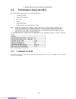
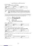
Страница 18: ... is not employed to correct arrival problems The Average Seek Time is measured as the weighted average of all possible seek combinations max 1 max 1 max max 1 n Tnout Tnin n Average Weighted Where max maximum seek length n seek length 1 to max Tnin inward measured seek time for an n track seek Tnout outward measured seek time for an n track seek 4 4 1 2 Full stroke seek Command Type Typical ms Max...

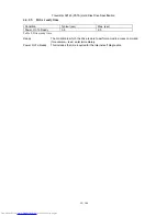
Страница 19: ...me Condition Typical sec Max sec Power On To Ready 3 5 9 5 Table 9 Drive ready time Ready The condition in which the drive is able to perform a media access command for example read write immediately Power On To Ready This includes the time required for the internal self diagnostics ...

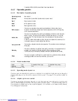
Страница 20: ...he device interface is capable of accepting commands The spindle motor is stopped All circuitry but the host interface is in power saving mode The execution of commands is delayed until the spindle becomes ready Sleep The device requires a soft reset or a hard reset to be activated All electronics including spindle motor and host interface are shut off 4 4 2 2 Mode transition time From To Transiti...

Страница 21: ...t yet written onto the disk In order to prevent this data loss confirm the completion of the actual write operation prior to the power off by issuing a Soft reset Hard reset Flush Cache command Standby command Standby Immediate command Sleep command Confirm the command s completion 5 3 Equipment status The equipment status is available to the host system any time the drive is not ready to read wri...

Страница 22: ... when specific conditions are met The drive does not report any auto reallocation to the host system The conditions for auto reallocation are described below 5 7 1 Nonrecovered write errors When a write operation cannot be completed after the Error Recovery Procedure ERP is fully carried out the sectors are reallocated to the spare location An error is reported to the host system only when the wri...

Страница 23: ...on capability The first 6 symbol of ECC are 4 check symbols for user data and the 2 symbol system ECC The other 34 symbols are Read Solomon ECC Hardware logic corrects up to 16 symbols 20 bytes errors on the fly 2 symbol System ECC is generated when HDC receives user data from HOST and can correct up to 1 symbol 10bit errors on the fly when one transfers to HOST ...

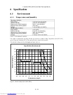
Страница 24: ...ture Maximum temperature gradient Altitude 40 to 65 C 5 to 95 noncondensing 40 C noncondensing 20 C hour 300 to 12 192 m 40 000 ft Table 11 Environmental condition The system is responsible for providing sufficient air movement to maintain surface temperatures below 60 C at the center of top cover and below 63 C at the center of the drive circuit board assembly The maximum storage period in the sh...

Страница 25: ... limits at the enclosure surface Frequency KHz Limits uT RMS 0 60 500 61 100 250 101 200 100 201 400 50 Table 12 Magnetic flux density limits 6 1 4 Conductive noise The disk drive shall work without soft error degradation in the frequency range from DC to 20 Mhz injected through any two of the mounting screw holes of the drive when an AC current of up to 45 mA p p is applied through a 50 ohm resis...

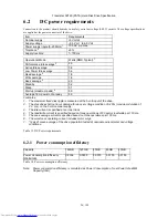
Страница 26: ...fixed disk ripple is measured at the 5 volt input of the drive 2 The disk drive shall not incur damage for an over voltage condition of 25 maximum duration of 20 ms on the 5 volt nominal supply 3 The idle current is specified at an inner track 4 The read write current is specified based on three operations of 63 sector read write per 100 ms 5 The seek average current is specified based on three op...

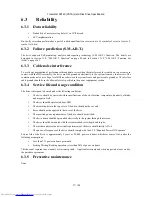
Страница 27: ...rement section 6 3 4 Service life and usage condition The drive is designed to be used under the following conditions The drive should be operated within specifications of shock vibration temperature humidity altitude and magnetic field The drive should be protected from ESD The breathing hole in the top cover of the drive should not be covered Force should not be applied to the cover of the drive...

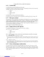
Страница 28: ...minimum of 20 000 emergency unloads 6 3 8 Required Power Off Sequence The required host system sequence for removing power from the drive is as follows Step 1 Issue one of the following commands Standby Standby immediate Sleep Note Do not use the Flush Cache command for the power off sequence because this command does not invoke Unload Step 2 Wait until the Command Complete status is returned In a...

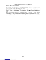
Страница 29: ...nds through the interface not by power cycling the drive Simple power cycling of the drive invokes the emergency unload mechanism and subjects the HDD to nontypical mechanical stress Power cycling testing may be required to test the boot up function of the system In this case HITACHI recommends that the power off portion of the cycle contain the sequence specified in section 6 4 6 2 Required Power...

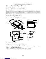
Страница 30: ...0 GB models 9 5 0 2 69 85 0 25 100 2 0 25 95 Max Table 15 Physical dimensions and weight 6 4 2 Mounting hole locations The mounting hole locations and size of the drive are shown below Figure 2 Mounting hole locations 6 4 3 Connector and jumper description A jumper is used to designate the drive address as either master or slave The jumper setting method is described in section 7 10 Drive address ...

Страница 31: ...nd vice versa The recommended mounting screw torque is 0 3 0 05 Nm The recommended mounting screw depth is 3 0 0 3 mm for bottom and 3 5 0 5 mm for horizontal mounting The user is responsible for using the appropriate screws or equivalent mounting hardware to mount the drive securely enough to prevent excessive motion or vibration of the drive at seek operation or spindle rotation 6 4 5 Load unloa...

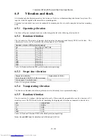
Страница 32: ... profile Breakpoint Hz m x 10n m 2 sec 4 Hz 5 1 9 x E 3 17 1 1 x E 1 45 1 1 x E 1 48 7 7 x E 1 62 7 7 x E 1 65 9 6 x E 1 150 9 6 x E 1 200 4 8 x E 2 500 4 8 x E 2 Table 16 Random vibration PSD profile breakpoints operating 6 5 3 Swept sine vibration Swept sine vibration zero to peak 5 to 500 to 5 Hz sine wave Sweep rate oct min 9 8 m sec2 1 G 5 500 Hz 1 0 Table 17 Swept sine vibration 6 5 4 Nonope...

Страница 33: ...hout a hard error while subjected to the following half sine shock pulse Duration of 1 ms Duration of 2 ms 1568 m sec2 160 G 3185 m sec2 325 G Table 19 Operating shock The input level shall be applied to the normal disk drive subsystem mounting points used to secure the drive in a normal system 6 5 8 Nonoperating shock The drive withstands the following half sine shock pulse without any data loss ...

Страница 34: ...mm above from the chamber floor No sound absorbing material shall be used The acoustical characteristics of the disk drive are measured under the following conditions Mode definitions Idle mode Power on disks spinning track following unit ready to receive and respond to control line commands Operating mode Continuous random cylinder selection and seek operation of the actuator with a dwell time at...

Страница 35: ...mmission FCC Rules and Regulations Class B Part 15 RFI Suppression German National Requirements RFI Japan VCCI Requirements of Hitachi products EU EMC Directive Technical Requirements and Conformity Assessment Procedures 6 8 1 CE Mark The product is certified for compliance with EC directive 89 336 EEC The EC marking for the certification appears on the drive 6 8 2 C Tick Mark The product complies...

Страница 36: ... material with a UL recognized flammability rating of V 1 or better except minor mechanical parts 6 9 5 Secondary circuit protection This product utilizes printed circuit wiring that must be protected against the possibility of sustained combustion due to circuit or component failures as defined in C B 2 4700 034 Protection Against Combustion Adequate secondary over current protection is the respo...

Страница 37: ...ctor The signal connector for AT attachment is designed to mate with Dupont part number 69764 044 or equivalent The figure below and Figure 6 5 2 on page 31 show the connector location and physical pin location 43 44 22 Pin Pin 19 1 2 A C B D Figure 3 Interface connector pin assignments Pin position 20 is left blank for correct connector insertion Pin positions A B C and D are used for the drive a...

Страница 38: ...er 42 5V motor power 43 GND 44 reserved Table 22 Signal definition O designates an output from the drive I designates an input to the drive I O designates an input output common OD designates an Open Drain output power designates a power supply to the drive reserved designates reserved pins which must be left unconnected The signal lines marked with are redefined during the Ultra DMA protocol to p...

Страница 39: ...se this signal is in high impedance state regardless of the state of the IRQ bit The interrupt is set when the IRQ bit is set by the drive CPU The IRQ is reset to zero by a host read of the status register or a write to the Command Register This signal is a 3 state line with 24 mA of sink capability DASP This is a time multiplexed signal which indicates that a drive is active or that device 1 is p...

Страница 40: ...he signal level of CSEL to one drive should be different from the signal level to another drive on the same AT interface cable to avoid master master or slave slave configurations KEY Pin position 20 has no connection pin It is recommended to close the respective position of the cable connector in order to avoid incorrect insertion IORDY This signal is an indication to the host that the drive is r...

Страница 41: ...rs between host and drive The STOP signal shall be asserted by the host prior to initiation of an Ultra DMA burst A STOP shall be negated by the host before data is transferred in an Ultra DMA burst Assertion of STOP by the host during or after data transfer in an Ultra DMA mode signals the termination of the burst DDMARDY Ultra DMA This signal is used only for Ultra DMA data transfers between hos...

Страница 42: ...ViH Voltage Input Low ViL 2 0 V min 5 5 V max 0 5 V min 0 8 V max Outputs Voltage output high at IoH min VoH Voltage output low at IoL min VoL 2 4 V min 0 5 V max Current Driver Sink Current IoL Driver Source Current IoH 16 mA min 400 µA min 7 6 Reset timings PARAMETER DESCRIPTION Min s Max s t1 RESET high to Not BUSY 9 5 t10 RESET low width 25 Figure 4 System reset timings t10 t1 RESET BUSY ...

Страница 43: ... t2 DIOR DIOW pulse width 70 t2i DIOR DIOW recovery time 25 t3 DIOW data setup 20 t4 DIOW data hold 10 t5 DIOR data setup 20 t6 DIOR data hold 5 t6z DIOR data tristate 30 t9 DIOR DIOW to address valid hold 10 tRD Read data valid to IORDY active 0 tA IORDY setup width 35 tB IORDY pulse width 1 250 Figure 5 PIO cycle timings t9 t0 t2 t2i t3 t4 t5 t1 tB Read data DD 15 0 DIOR DIOW CS 1 0 DA 2 0 Write...

Страница 44: ...e width 70 tE DIOR data access 50 tF DIOR data hold 5 tG DIOR DIOW data setup 20 tH DIOW data hold 10 tI DMACK to DIOR DIOW setup 0 tJ DIOR DIOW to DMACK hold 5 tKR tKW DIOR negated pulse width DIOW negated pulse width 25 tLR tLW DIOR to DMARQ delay DIOW to DMARQ delay 35 tZ DMACK to read data released 25 Figure 6 Multiword DMA cycle timings WRITE DD 15 0 READ DD 15 0 DMACK DMARQ DIOR DIOW t0 tLR ...

Страница 45: ...70 20 55 20 55 20 50 tZIORD Minimum time before driving IORDY 0 0 0 0 0 0 tFS First DSTROBE time 0 230 0 200 0 170 0 130 0 120 0 90 tCYC Cycle time 112 73 54 39 25 16 8 t2CYC Two cycle time 230 154 115 86 57 38 tAZ Maximum time allowed for output drivers to release 10 10 10 10 10 10 tAZD Drivers to assert 0 0 0 0 0 0 tDS Data setup time at host 15 10 7 7 5 4 tDH Data hold time at host 5 5 5 5 5 4 ...

Страница 46: ...ns MIN ns MAX ns MIN ns MAX ns MIN ns MAX ns MIN ns MAX ns tSR DSTROBE to HDMARDY time 50 30 20 tRFS HDMARDY to final DSTROBE time 75 70 60 60 60 50 Figure 8 Ultra DMA cycle timings Host Pausing Read Note When a host does not satisfy the tSR timing the host should be ready to receive two more data words after HDMARDY is negated DSTROBE HDMARDY DMACK DMARQ tSR STOP tRFS ...

Страница 47: ...mum time allowed for output drivers to release 10 10 10 10 10 10 tZAH Minimum delay time required for output 20 20 20 20 20 20 tMLI Interlock time with minimum 20 20 20 20 20 20 tDS CRC word setup time at device 15 10 7 7 5 4 tDH CRC word hold time at device 5 5 5 5 5 4 6 tACK Hold time DMACK negation 20 20 20 20 20 20 tIORDYZ Maximum time before releasing IORDY 20 20 20 20 20 20 Figure 9 Ultra DM...

Страница 48: ...for output drivers to release 10 10 10 10 10 10 tZAH Maximum delay time required for output 20 20 20 20 20 20 tMLI Interlock time with minimum 20 20 20 20 20 20 tDS CRC word setup time at device 15 10 7 7 5 4 tDH CRC word hold time at device 5 5 5 5 5 4 6 tACK Hold time for DMACK negation 20 20 20 20 20 tIORDYZ Maximum time before releasing IORDY 20 20 20 20 20 Figure 10 Ultra DMA cycle timings De...

Страница 49: ...70 20 70 20 70 20 55 20 55 20 55 tZIORDY Minimum time before driving HSTROBE 0 0 0 0 0 0 tLI Limited interlock time 0 150 0 150 0 150 0 100 0 100 0 75 tCYC Cycle time 112 73 54 39 25 16 8 T2CYC Two cycle time 230 154 115 86 57 38 tDS Data setup time at device 15 10 7 7 5 4 tDH Data Hold time at device 5 5 5 5 5 4 6 Figure 11 Ultra DMA cycle timings Initiating Write HSTROBE DDMARDY DMACK DMARQ STOP...

Страница 50: ... ns MIN ns MAX ns MIN ns MAX ns MIN ns MAX ns MIN ns MAX ns tSR HSTROBE to DDMARDY time 50 30 20 tRFS DDMARDY to final HSTROBE time 75 70 60 60 60 50 Figure 12 Ultra DMA cycle timings Device Pausing Write Note When a device does not satisfy the tSR timing the device is ready to receive two more data words after DDMARDY is negated HSTROBE DDMARDY DMACK DMARQ tSR STOP tRFS ...

Страница 51: ...0 100 85 tLI Limited interlock time 0 150 0 150 0 150 0 100 0 100 0 75 tMLI Interlocking time 20 20 20 20 20 20 tDS CRC word setup time at device 15 10 7 7 5 4 tDH CRC word hold time at device 5 5 5 5 5 4 6 tACK Hold time for DMACK negation 20 20 20 20 20 20 tIORDYZ Maximum time before releasing IORDY 20 20 20 20 20 20 Figure 13 Ultra DMA cycle timings Device Terminating Write HSTROBE DDMARDY DMAC...

Страница 52: ...ed interlock time 0 150 0 150 0 150 0 100 0 100 0 75 tMLI Interlock time 20 20 20 20 20 20 tDS CRC word setup time at device 15 10 7 7 5 4 tDH CRC word hold time at device 5 5 5 5 5 4 6 tACK Hold time for DMACK negation 20 20 20 20 20 20 tIORDYZ Maximum time before releasing IORDY 20 20 20 20 20 20 Figure 14 Ultra DMA cycle timings Host Terminating Write HSTROBE DDMARDY DMACK DMARQ STOP tMLI DD 15...

Страница 53: ... Setting 2 Device 1 Slave Setting 3 Cable Select Setting 4 Never attach a jumper here Setting 5 Never attach a jumper here When pin C is grounded the drive does not spin up at POR When the drive address is Cable Select the address depends on the condition of pin 28 of the AT interface cable If pin 28 is ground or low the drive is a Master If pin 28 is open or logic high the drive is a Slave 7 10 1...

Страница 54: ...used to address the Command Block registers while the CS1 is used to address Control Block registers The following table shows the I O address map CS0 CS1 DA02 DA01 DA00 DIOR 0 Read DIOW 0 Write Command Block Registers 0 1 0 0 0 Data Reg Data Reg 0 1 0 0 1 Error Reg Features Reg 0 1 0 1 0 Sector count Reg Sector count Reg 0 1 0 1 1 LBA low Reg LBA low Reg 0 1 1 0 0 LBA mid Reg LBA mid Reg 0 1 1 0 ...

Страница 55: ...Travelstar 5K160 PATA Hard Disk Drive Specification 55 188 Part 2 Interface Specification ...

Страница 56: ...with certain limitations described in 9 Deviations from Standard on page 57 HTS5416XXJ9AT00 support following functions as Vendor Specific Function Address Offset Feature Format Unit Function SENSE CONDITION command 8 2 Terminology Device Device indicates HTS5416XXJ9AT00 Host Host indicates the system that the device is attached to First Command The command which is executed first right after powe...

Страница 57: ... ATAPI 7 Revision 4b dated 21 Apr 2004 with deviation as follows S M A R T Return Status S M A R T RETURN STATUS subcommand does not check advisory attributes That is the device will not report threshold exceeded condition unless prefailure attributes exceed their corresponding thresholds For example Power On Hours Attribute never results in negative reliability status 10 Physical Interface Physic...

Страница 58: ...et Communication to or from the device is through an I O Register that routes the input or output data to or from registers addressed by the signals from the host CS0 CS1 DA2 DA1 DA0 DIOR and DIOW The Command Block Registers are used for sending commands to the device or posting status from the device The Control Block Registers are used for device control and to post alternate status Cylinder Hig...

Страница 59: ... device interrupts to the host will be enabled When IEN 1 or the device is not selected device interrupts to the host will be disabled 11 5 Drive Address Register Drive Address Register 7 6 5 4 3 2 1 0 HIZ WTG H3 H2 H1 H0 DS1 DS0 Figure 19 Drive Address Register This register contains the inverted drive select and head select addresses of the currently selected drive Bit Definitions HIZ High Imped...

Страница 60: ... error or an invalid parameter in an output register TK0NF T0N Track 0 Not Found T0N 1 indicates track 0 was not found during a Recalibrate command AMNF AMN Address Mark Not Found AMN 1 indicates the data address mark has not been found after finding the correct ID field for the requested sector This bit is obsolete 11 8 Features Register This register is command specific This is used with the Set...

Страница 61: ... any register when BSY 1 the contents of the Status Register will be returned DRDY RDY Device Ready RDY 1 indicates that the device is capable of responding to a command RDY will be set to 0 during power on until the device is ready to accept a command DF Device Fault DF 1 indicates that the device has detected a write fault condition DF is set to 0 after the Status Register is read by the host DS...

Страница 62: ...ng Host interface o o Aborting Device operation 1 1 Initialization of hardware O x x Internal diagnostic O x x Starting spindle motor 5 x x Initialization of registers 2 O o o DASP handshake O o x PDIAG handshake O o o Reverting programmed parameters to default O o 3 Number of CHS set by Initialize Device Parameter Multiple mode Write cache Read look ahead ECC bytes Volatile max address Address of...

Страница 63: ...A Low 01h LBA Mid 00h LBA High 00h Device A0h Status 50h Alternate Status 50h Figure 24 Default Register Values The meaning of the Error Register diagnostic codes resulting from power on hard reset or the Execute Device Diagnostic command are shown in the following table Code Description 01h No error Detected 02h Formatter device error 03h Sector buffer error 04h ECC circuitry error 05h Controller...

Страница 64: ... to clear the BSY bit and whether Device 1 has reset without any errors otherwise Device 0 shall simply reset and clear the BSY bit DASP is asserted by Device 0 and Device 1 if it is present in order to indicate device active Execute Device Diagnostic If Device 1 is present Device 0 shall read PDIAG to determine when it is valid to clear the BSY bit and if Device 1 passed or failed the EXECUTE DEV...

Страница 65: ...ntrollable without a normal seek current profile Emergency unload is intended to be invoked in rare situations Because this operation is inherently uncontrolled it is more mechanically stressful than a normal unload A single emergency unload operation is more stressful than 100 normal unloads Use of emergency unload reduces the start stop life of the HDD at a rate at least 100X faster than that of...

Страница 66: ...h Cylinders are numbered from 0 to the maximum value allowed by the current CHS translation mode but cannot exceed 65535 0FFFFh When the host selects a CHS translation mode using the INITIALIZE DEVICE PARAMETERS command the host requests the number of sectors per logical track and the number of heads per logical cylinder The device then computes the number of logical cylinders available in request...

Страница 67: ... command allows a host to determine if a device is currently in going to or leaving standby mode The Idle and Idle Immediate commands move a device to idle mode immediately from the active or standby modes The idle command also sets the standby timer count and starts the standby timer The sleep command moves a device to sleep mode The device s interface becomes inactive at the completion of the sl...

Страница 68: ...not be accessible Though the interface is inactive in sleep mode the access to the interface registers and the validity of INTRQ is guaranteed for two seconds after Sleep command is completed After this period the contents of interface registers may be lost Since the contents of interface registers may be invalid host should NOT check Status register nor Alternate Status register prior to issuing ...

Страница 69: ...diately after Active mode command processing is complete instead of conventional idle mode In Performance Idle mode all electronic components remain powered and full frequency servo remains operational This provides instantaneous response to the next command The duration of this mode is intelligently managed as described below 12 6 2 Active Idle mode In this mode power consumption is 45 55 less th...

Страница 70: ...is algorithms being used by the device are predicting a lower probability of a degrading or fault condition existing Accordingly lower attribute values indicate that the analysis algorithms being used by the device are predicting a higher probability of a degrading or fault condition existing There is no implied linear reliability relationship corresponding to the numerical relationship between di...

Страница 71: ...curity When the device lock function is enabled and the User Password is forgotten then only the Master Password with a Security Erase Unit command can unlock the device Then user data is erased 12 8 3 Password This function can have 2 types of passwords as described below Master Password When the Master Password is set the device does NOT enable the Device Lock Function and the device can NOT be ...

Страница 72: ...160 PATA Hard Disk Drive Specification 72 188 12 8 5 2 User Password setting When a User Password is set the device will automatically enter lock mode the next time the device is powered on Figure 29 Initial Setting ...

Страница 73: ... 30 Usual Operation 12 8 5 4 User Password Lost If the User Password is forgotten and High level security is set the system user can t access any data However the device can be unlocked using the Master Password If a system user forgets the User Password and Maximum security level is set data access is impossible However the device can be unlocked using the Security Erase Unit command to unlock th...

Страница 74: ...by using various passwords many times The device counts the password mismatch If the password does not match the device counts it up without distinguishing the Master password and the User password If the count reaches 5 EXPIRE bit bit 4 of Word 128 in Identify Device information is set and then SECURITY ERASE UNIT command and SECURITY UNLOCK command are aborted until a hard reset or a power off T...

Страница 75: ... o o Format Unit x o o Identify Device o o o Idle o o o Idle Immediate o o o Idle Immediate with Unload Feature o o o Initialize Device Parameters o o o Read Buffer o o o Read DMA x o o Read DMA EXT x o o Read Long x o o Read Multiple x o o Read Multiple EXT x o o Read Native Max ADDRESS o o o Read Native Max ADDRESS EXT o o o Read Sector s x o o Read Sector s EXT x o o Read Verify Sector s x o o ...

Страница 76: ... o o o S M A R T Enable Operations o o o S M A R T Execute Off line Immediate o o o S M A R T Read Attribute Values o o o S M A R T Read Attribute Thresholds o o o S M A R T Read log sector o o o S M A R T Write log sector o o o S M A R T Return Status o o o S M A R T Save Attribute Values o o o Standby o o o Standby Immediate o o o Write Buffer o o o Write DMA x o o Write DMA EXT x o o Write DMA ...

Страница 77: ...cturer Special utility software is required to define the size of protected area and store the data into it The sequence is Issue Read Native Max ADDRESS command to get the real device max of LBA CYL Returned value shows that native device Max LBA is 0FFFFFh regardless to the current setting Make entire device be accessible including the protected area by setting device Max LBA as 0FFFFFh via Set ...

Страница 78: ...he device from the Set Max Locked mode to the Set Max Unlocked mode This command requests a transfer of a single sector of data from the host The figure shown above defines the content of this sector of information The password supplied in the sector of data transferred is compared with the stored Set Max password If the password compare fails then the device returns command aborted and decrements...

Страница 79: ...eset or Power on Reset If Reverting to Power on Defaults has been enabled by Set Features command it is cleared by Soft reset as well Upon entering offset mode the capacity of the drive returned in the Identify Device data is the size of the former protected area A subsequent Set Max Address command with the address returned by Read Max Address command allows access to the entire drive Addresses w...

Страница 80: ...eek commands is the total accumulated time for the actual seek operation plus one pre and post overhead When the number of seeks is large just this one overhead can be ignored Figure 37 Seek overlap 12 12 Write Cache Function Write cache is a performance enhancement whereby the device reports completion of the write command Write Sector s and Write Multiple to the host as soon as the device has re...

Страница 81: ...s from Cylinder 0 The conditions for auto reallocation are described below Non recovered write errors When a write operation can not be completed after the Error Recovery Procedure ERP is fully carried out the sector s are reallocated to the spare location An error is reported to the host system only when the write cache is disabled and the auto reallocation fails If the number of available spare ...

Страница 82: ...s moved to previous content location The host may read the previous content of the Features the Sector Count the LBA Low Mid High registers by first setting the High Order Bit HOB bit 7 of the Device control register to one and then reading the desired register If HOB in the Device Control register is cleared to zero the host reads the most recently written content when the register is read A writ...

Страница 83: ...es on page 179 shows the device timeout values 13 1 Data In Commands These commands are Device Configuration IDENTIFY Identify Device Read Buffer Read Long Read Multiple Read Multiple EXT Read Sector s Read Sector s EXT S M A R T Read Attribute Values S M A R T Read Attribute Thresholds S M A R T Read log sector Execution includes the transfer of one or more 512 byte 512 bytes on Read Long sectors...

Страница 84: ...y setting BSY 0 ERR 1 ABT 1 and interrupting the host If an error occurs the device will set BSY 0 ERR 1 and DRQ 1 The device will then store the error status in the Error Register and interrupt the host The registers will contain the location of the sector in error The erroneous location will be reported with CHS mode or LBA mode the mode is decided by mode select bit bit 6 of Device register on ...

Страница 85: ...data to be transferred A The device sets BSY 0 and DRQ 1 when it is ready to receive a sector or block B The host writes one sector or block of data via the Data Register C The device sets BSY 1 after it has received the sector or block D When the device has finished processing the sector or block it sets BSY 0 and interrupts the host E In response to the interrupt the host reads the Status Regist...

Страница 86: ... ABT 1 and interrupting the host If an uncorrectable error occurs the device will set BSY 0 and ERR 1 store the error status in the Error Register and interrupt the host The registers will contain the location of the sector in error The errored location will be reported with CHS mode or LBA mode The mode is decided by mode select bit bit 6 of Device register on issuing the command All data transfe...

Страница 87: ...ediate Initialize Device Parameters Read Native Max ADDRESS Read Native Max ADDRESS EXT Read Verify Sector s Read Verify Sector s EXT Recalibrate Security Erase Prepare Security Freeze Lock Seek Sense condition Set Features Set Max ADDRESS Set Max ADDRESS EXT Set Max LOCK Set Max FREEZE LOCK Set Multiple Mode Sleep S M A R T Disable Operations S M A R T Enable Disable Attribute Autosave S M A R T ...

Страница 88: ...he host writes any required parameters to the Features Sector Count LBA High LBA Mid LBA Low and Device Registers 2 The host writes the command code to the Command Register 3 The device sets BSY 1 4 When the device has finished processing the command it sets BSY 0 and interrupts the host 5 In response to the interrupt the host reads the Status Register 6 The device clears the interrupt in response...

Страница 89: ... are issued on multi sector commands the host resets the DMA channel prior to reading status from the device The DMA protocol allows high performance multi tasking operating systems to eliminate processor overhead associated with PIO transfers 1 Host initializes the slave DMA channel 2 Host writes any required parameters to the Features Sector Count LBA High LBA Mid LBA Low and Device registers 3 ...

Страница 90: ...1 1 0 0 1 0 0 0 1 1 Read Buffer E4 1 1 1 0 0 1 0 0 4 Read DMA C8 1 1 0 0 1 0 0 0 4 Read DMA C9 1 1 0 0 1 0 0 1 4 Read DMA EXT 25 0 0 1 0 0 1 0 1 1 Read Log Ext 2F 0 0 1 0 1 1 1 1 1 Read Long 22 0 0 1 0 0 0 1 0 1 Read Long 23 0 0 1 0 0 0 1 1 1 Read Multiple C4 1 1 0 0 0 1 0 0 1 Read Multiple EXT 29 0 0 1 0 1 0 0 1 3 Read Native Max ADDRESS F8 1 1 1 1 1 0 0 0 3 Read Native Max ADDRESS EXT 27 0 0 1 0...

Страница 91: ...0 1 0 1 1 0 0 0 0 3 S M A R T Return Status B0 1 0 1 1 0 0 0 0 3 S M A R T Save Attribute Values B0 1 0 1 1 0 0 0 0 2 S M A R T Write Log Sector B0 1 0 1 1 0 0 0 0 3 Standby E2 1 1 1 0 0 0 1 0 3 Standby 96 1 0 0 1 0 1 1 0 3 Standby Immediate E0 1 1 1 0 0 0 0 0 3 Standby Immediate 94 1 0 0 1 0 1 0 0 2 Write Buffer E8 1 1 1 0 1 0 0 0 4 Write DMA CA 1 1 0 0 1 0 1 0 4 Write DMA CB 1 1 0 0 1 0 1 1 4 Wr...

Страница 92: ... Enable Automatic Acoustic management AAM EF 42 52 bytes of ECC apply on Read Write Long EF 44 Disable read look ahead feature EF 55 Disable reverting to power on defaults EF 66 Disable write cache EF 82 Disable Advanced Power Management feature EF 85 Disable Power Up in Standby feature EF 86 Disable Address Offset mode EF 89 Enable read look ahead feature EF AA 4 bytes of ECC apply on Read Write ...

Страница 93: ...ndicates that the Option Bit of the Sector Count Register should be specified This bit is used by Set Max ADDRESS command V Valid Indicates that the bit is part of an output parameter and should be specified x Indicates that the hex character is not used Indicates that the bit is not used Input Registers 0 Indicates that the bit is always set to 0 1 Indicates that the bit is always set to 1 H Head...

Страница 94: ... See Below Error Register Status Register 7 6 5 4 3 2 1 0 7 6 5 4 3 2 1 0 CRC UNC 0 IDN 0 ABT T0N AM N BSY RDY DF DSC DRQ COR IDX ERR 0 0 0 0 0 V 0 0 0 0 0 0 V Figure 41 Check Power Mode Command E5h 98h The Check Power Mode command will report whether the device is spun up and the media is available for immediate access Input Parameters From The Device Sector Count The power mode code The command ...

Страница 95: ...ORE subcommand C0h The DEVICE CONFIGURATION RESTORE command discard any setting previously made by a DEVICE CONFIGURATION SET command and return the content of the IDENTIFY DEVICE command response to the original settings as indicated by the data returned from the execution of a DEVICE CONFIGURATION IDENTIFY command 14 2 2 DEVICE CONFIGURATION FREEZE LOCK subcommand C1h The DEVICE CONFIGURATION FR...

Страница 96: ...son code is returned to sector count register invalid word location is returned to LBA High register and invalid bit location is returned to LBA Mid register The Definition of error information is shown on the next page ERROR INFORMATION EXAMPLE 1 After establish a protected area with SET MAX address if a user attempts to execute DC SET or DC RESTORE device abort that command and return error reas...

Страница 97: ... the byte consisting of bits 7 0 of word 255 Each byte is added with unsigned arithmetic and overflow is ignored The sum of all bytes is zero when the checksum is correct LBA High invalid word location LBA Mid invalid bit location bits 7 0 LBA Low invalid bit location bits 15 8 Sector count error reason code description 01h DCO feature is frozen 02h Device is now Security Locked mode 03h Device s ...

Страница 98: ... Status See Below Error Register Status Register 7 6 5 4 3 2 1 0 7 6 5 4 3 2 1 0 CRC UNC 0 IDN 0 ABT T0N AM N BSY RDY DF DSC DRQ COR IDX ERR 0 V V V V V V V 0 0 0 0 0 Figure 46 Execute Device Diagnostic Command 90h The Execute Device Diagnostic command performs the internal diagnostic tests implemented by the device The results of the test are stored in the Error Register The normal Error Register...

Страница 99: ...High LBA High Device D Device Command 1 1 1 0 0 1 1 1 Status See Below Error Register Status Register 7 6 5 4 3 2 1 0 7 6 5 4 3 2 1 0 CRC UNC 0 IDN 0 ABT T0N AM N BSY RDY DF DSC DRQ COR IDX ERR 0 0 0 0 0 V 0 0 0 V 0 V 0 V Figure 47 Flush Cache Command E7h This command causes the device to complete writing data from its cache The device returns a status RDY 1 and DSC 1 50h after following sequence ...

Страница 100: ...HOB 0 LBA Low Previous LBA Low HOB 1 Current HOB 0 LBA Mid Previous LBA Mid HOB 1 Current HOB 0 LBA High Previous LBA High HOB 1 Device Head D Device Head Command 1 1 1 0 1 0 1 0 Status See Below Error Register Status Register 7 6 5 4 3 2 1 0 7 6 5 4 3 2 1 0 CRC UNC 0 IDN 0 ABT T0N AMN BSY RDY DF DSC DRQ COR IDX ERR 0 0 0 0 0 V 0 0 0 V 0 V 0 V Figure 48 Flush Cache EXT Command EAh This command cau...

Страница 101: ...ack will be initialized to zero with write operation At this time whether the sector of data is initialized correctly is not verified with read operation Any data previously stored on the track will be lost Output Parameters To The Device LBA Low In LBA mode this register specifies LBA address bits 0 7 to be formatted L 1 LBA High Mid The cylinder number of the track to be formatted L 0 In LBA mod...

Страница 102: ...ommand completion and are also used on next power on reset or hard reset Both previous information are erased from the device by this command Note that the Format Unit command initializes from LBA 0 to Native MAX LBA Host MAX LBA set by Initialize Drive Parameter or Set MAX ADDRESS command is ignored So the protected area by Set MAX ADDRESS commands is also initialized The security erase prepare c...

Страница 103: ...ister 7 6 5 4 3 2 1 0 Data Data Feature Error See Below Sector Count Sector Count LBA Low LBA Low LBA Mid LBA Mid LBA High LBA High Device D Device Command 1 1 1 0 1 1 0 0 Status See Below Error Register Status Register 7 6 5 4 3 2 1 0 7 6 5 4 3 2 1 0 CRC UNC 0 IDN 0 ABT T0N AM N BSY RDY DF DSC DRQ COR IDX ERR 0 0 0 0 0 V 0 0 0 V 0 0 V Figure 51 Identify Device Command ECh ...

Страница 104: ...ion C837h SET FEATURES subcommand is not required to spin up and IDENTIFY DEVICE response is complete 37C8h SET FEATURES subcommand is required to spin up and IDENTIFY DEVICE response is incomplete 03 Note 2 Number of heads in default translate mode 04 05 0 Reserved 06 003FH Number of sectors per track in default translate mode 07 09 0 Reserved 10 19 XXXX Serial number in ASCII 0 not specified 20 ...

Страница 105: ...eserved 2 1 1 Word 88 is Valid 1 1 1 Word 64 70 are Valid 0 1 1 Word 54 58 are Valid 54 xxxxH Number of current cylinders 55 xxxxH Number of current heads 56 xxxxH Number of current sectors per track 57 58 xxxxH Current capacity in sectors Word 57 specifies the low word of the capacity 59 0xxxH Current Multiple setting bit assignments 15 9 0 Reserved 8 1 Multiple Sector Setting is Valid 7 0 xxh Cu...

Страница 106: ...m PIO Transfer Cycle Time With IORDY Flow Control 15 0 78h Cycle time in nanoseconds 120ns 16 6MB s 69 79 0000H Reserved 80 00FCH Major version number ATA 1 2 3 and ATA ATAPI 4 5 6 7 81 001AH Minor version number ATA ATAPI 7 T13 1532D revision 1 82 746BH Command set supported 15 0 Reserved 14 1 1 NOP command supported 13 1 1 READ BUFFER command supported 12 1 1 WRITE BUFFER command supported 11 0 ...

Страница 107: ...orted 0 1 1 DOWNLOAD MICROCODE command supported 84 4163H Command set feature supported extension 15 0 Always 14 1 Always 13 0 1 IDLE IMMEDIATE with UNLOAD FEATURE supported 12 11 0 Reserved 10 0 1 URG bit supported for WRITE STREAM DMA EXT and WRITE STREAM EXT 9 0 1 URG bit supported for READ STREAM DMA EXT and READ STREAM EXT 8 1 1 64 bit World wide name supported 7 0 1 WRITE DMA QUEUED FUA EXT ...

Страница 108: ...1 FLUSH CACHE EXT command supported 12 1 1 FLUSH CACHE command supported 11 x 1 Device Configuration Overlay supported 10 1 1 48 bit Address feature set supported 9 x 1 Automatic Acoustic Management enabled 8 x 1 SET MAX security extension enabled 7 x 1 Address Offset mode enabled 6 1 1 SET FEATURES subcommand required to spin up 5 x 1 Power Up In Standby feature set has been enabled via the SET F...

Страница 109: ...aDMA mode 4 is selected 11 x 1 UltraDMA mode 3 is selected 10 x 1 UltraDMA mode 2 is selected 9 x 1 UltraDMA mode 1 is selected 8 x 1 UltraDMA mode 0 is selected 7 0 Reserved 6 0 1 UltraDMA mode 6 is supported 5 1 1 UltraDMA mode 5 is supported 4 1 1 UltraDMA mode 4 is supported 3 1 1 UltraDMA mode 3 is supported 2 1 1 UltraDMA mode 2 is supported 1 1 1 UltraDMA mode 1 is supported 0 1 1 UltraDMA ...

Страница 110: ...evice number 00 Reserved 01 a jumper was used 10 the CSEL signal was used 11 some other method was used or the method is unknown 0 1 Always 94 80xxH Automatic Acoustic Management value 15 8 Vendor s Recommended Acoustic Management level 7 0 Current Automatic Acoustic Management value Default value is FEh 95 0000H Stream Minimum Request Size 96 0000H Streaming Transfer Time DMA 97 0000H Streaming A...

Страница 111: ...Reserved 5 0 1 Enhanced security erase supported 4 x 1 Security count expired 3 x 1 Security Frozen 2 x 1 Security locked 1 x 1 Security enabled 0 1 1 Security supported 129 000xH Current Set Feature Option Bit assignments 15 4 0 Reserved 3 x 1 Auto reassign enabled 2 x 1 Reverting enabled 1 x 1 Read Look ahead enabled 0 x 1 Write Cache enabled 130 xxxxH Reserved 131 000xH Initial Power Mode Selec...

Страница 112: ...ss for 48 bit Address feature set word 100 103 12A19EB0h DF94BB0h Model Number in ASCII Hitachi HTS541680J9AT00 Hitachi HTS541660J9AT00 Hitachi HTS541640J9AT00 Number of cylinders 3FFFh 3FFFh 3FFFh Number of heads 10h 10h 10h Buffer size 3AB0h 3AB0h 3AB0h Total number of user addressable sectors word 60 61 950F8B0h 6FC7C80h 4A85300h Maximum user LBA address for 48 bit Address feature set word 100 ...

Страница 113: ...le mode immediately and set auto power down timeout parameter standby timer And then the timer starts counting down When the device s power save mode is already any idle mode the device keeps that mode When the Idle mode is entered the device is spun up to operating speed If the device is already spinning the spin up sequence is not executed During Idle mode the device is spinning and ready to res...

Страница 114: ...4 3 2 1 0 7 6 5 4 3 2 1 0 CRC UNC 0 IDN 0 ABT T0N AM N BSY RDY DF DSC DRQ COR IDX ERR 0 0 0 0 0 V 0 0 0 V 0 V 0 V Figure 62 Idle Immediate Command E1h 95h The Idle Immediate command causes the device to enter performance Idle mode The device is spun up to operating speed If the device is already spinning the spin up sequence is not executed During Idle mode the device is spinning and ready to resp...

Страница 115: ...V 0 0 0 0 0 0 V Figure 63 Initialize Device Parameters Command 91h The Initialize Device Parameters command enables the host to set the number of sectors per track and the number of heads minus 1 per cylinder Words 54 58 in Identify Device Information reflects these parameters The parameters remain in effect until the following events Another Initialize Device Parameters command is received The de...

Страница 116: ...ister Status Register 7 6 5 4 3 2 1 0 7 6 5 4 3 2 1 0 CRC UNC 0 IDN 0 ABT T0N AM N BSY RDY DF DSC DRQ COR IDX ERR 0 0 0 0 0 V 0 0 0 V 0 0 V Figure 64 Read Buffer Command E4h The Read Buffer command transfers a sector of data from the sector buffer of device to the host The sector is transferred through the Data Register 16 bits at a time The sector transferred will be from the same part of the buf...

Страница 117: ... data transfer has terminated and status is available If an uncorrectable error occurs the read will be terminated at the failing sector Output Parameters To The Device Sector Count The number of continuous sectors to be transferred If zero is specified then 256 sectors will be transferred LBA Low The sector number of the first sector to be transferred L 0 In LBA mode this register specifies LBA a...

Страница 118: ...ta Register 16 bits at a time The host initializes a slave DMA channel prior to issuing the command The data transfers are qualified by DMARQ and are performed by the slave DMA channel The device issues only one interrupt per command to indicate that data transfer has terminated and status is available If an uncorrectable error occurs the read will be terminated at the failing sector Output Parame...

Страница 119: ...7 0 The log transferred by the drive shall start at the sector in the specified log at the specified offset regardless of the sector count requested Sector Count Previous The number of sectors to be read from the specified log high orders bits 15 8 LBA Low Current The log to be returned as described in Figure LBA Mid Current The first sector of the log to be read low order bits 7 0 LBA Mid Previou...

Страница 120: ...ed comprehensive SMART error log Figure 53 defines the format of each of the sectors that comprise the Extended Comprehensive SMART error log Error log data structure shall not include errors attributed to the receipt of faulty commands such as command codes not implemented by the device or requests with invalid parameters or in valid addresses Description Bytes Offset SMART error log version 1 00...

Страница 121: ...ter 7 0 see Note 1 01h Features register 15 8 1 02h Sector count register 7 0 1 03h Sector count register 15 8 1 04h Sector number register 7 0 1 05h Sector number register 15 8 1 06h Cylinder Low register 7 0 1 07h Cylinder Low register 15 8 1 08h Cylinder High register 7 0 1 09h Cylinder High register 15 8 1 0Ah Device Head register 1 0Bh Command register 1 0Ch Reserved 1 0Dh Timestamp milliseco...

Страница 122: ... during the life of the device This count shall not include errors attributed to the receipt of faulty commands such as commands codes not implemented by the device or requests with invalid parameters or invalid addresses If the maximum value for this field is reached the count shall remain at the maximum value when additional errors are encountered and logged 14 15 3Extended Self test log sector ...

Страница 123: ...er shall be 01h 14 15 3 2 Self test descriptor index This indicates the most recent self test descriptor If there have been no self tests this is set to zero Valid values for the Self test descriptor index are 0 to 18 14 15 3 3 Extended Self test log descriptor entry The content of the self test descriptor entry is shown below Description Bytes Offset Self test number 1 00h Self test execution sta...

Страница 124: ... command makes a single attempt to read the data and does not check the data using ECC Whatever is read is returned to the host Output Parameters To The Device Sector Count The number of continuous sectors to be transferred The Sector Count must be set to one LBA Low The sector number of the sector to be transferred L 0 In LBA mode this register contains LBA bits 0 7 L 1 LBA High Mid The cylinder ...

Страница 125: ...t an interrupt is generated for each block as defined by the Set Multiple command instead of for each sector Output Parameters To The Device Sector Count The number of continuous sectors to be transferred If zero is specified then 256 sectors will be transferred LBA Low The sector number of the first sector to be transferred L 0 In LBA mode this register contains LBA bits 0 7 L 1 LBA High Mid The ...

Страница 126: ... UNC 0 IDN 0 ABT T0N AMN BSY RDY DF DSC DRQ COR IDX ERR 0 V 0 V 0 V 0 0 0 V 0 V 0 V Figure 78 Read Multiple EXT 29h Output Parameters To The Device Sector Count Current The number of sectors to be transferred low order bits 7 0 Sector Count Previous The number of sectors to be transferred high order bits 15 8 If 0000h in the Sector Count register is specified then 65 536 sectors will be transferre...

Страница 127: ...max address is greater than 268 435 455 the Read Native Max Address command return a value of 268 435 455 Output Parameters To The Device L LBA mode Indicates the addressing mode L 0 specifies CHS mode and L 1 does LBA addressing mode D The device number bit Indicates that the device number bit of the Device Register should be specified D 0 selects the master device and D 1 selects the slave devic...

Страница 128: ... V Device 1 D Device V Command 0 0 1 0 0 1 1 1 Status See Below Error Register Status Register 7 6 5 4 3 2 1 0 7 6 5 4 3 2 1 0 CRC UNC 0 IDN 0 ABT T0N AMN BSY RDY DF DSC DRQ COR IDX ERR 0 0 0 0 0 V 0 0 0 V 0 0 V Figure 80 Read Native Max ADDRESS EXT 29h This command returns the native max LBA of HDD which is not effected by Set Max ADDRESS EXT command Input Parameters From The Device LBA Low HOB 0...

Страница 129: ...ad will be terminated at the failing sector Output Parameters To The Device Sector Count The number of continuous sectors to be transferred If zero is specified then 256 sectors will be transferred LBA Low The sector number of the first sector to be transferred L 0 In LBA mode this register contains LBA bits 0 7 L 1 LBA High Mid The cylinder number of the first sector to be transferred L 0 In LBA ...

Страница 130: ...and reads from 1 to 65 536 sectors of data from disk media then transfers the data from the device to the host The sectors are transferred through the Data Register 16 bits at a time If an uncorrectable error occurs the read will be terminated at the failing sector Output Parameters To The Device Sector Count Current The number of sectors to be transferred low order bits 7 0 Sector Count Previous ...

Страница 131: ...ble error occurs the read verify will be terminated at the failing sector Output Parameters To The Device Sector Count The number of continuous sectors to be verified If zero is specified then 256 sectors will be verified LBA Low The sector number of the first sector to be transferred L 0 In LBA mode this register contains LBA bits 0 7 L 1 LBA High Mid The cylinder number of the first sector to be...

Страница 132: ...ctors on the device No data is transferred to the host The difference between the Read Sector s Ext command and the Read Verify Sector s Ext command is whether the data is transferred to the host or not If an uncorrectable error occurs the Read Verify Sector s Ext will be terminated at the failing sector Output Parameters To The Device Sector Count Current The number of sectors to be transferred l...

Страница 133: ... LBA Low LBA Mid LBA Mid LBA High LBA High Device D Device Command 0 0 0 1 Status See Below Error Register Status Register 7 6 5 4 3 2 1 0 7 6 5 4 3 2 1 0 CRC UNC 0 IDN 0 ABT T0N AM N BSY RDY DF DSC DRQ COR IDX ERR 0 0 0 0 0 V V 0 0 V 0 V 0 V Figure 85 Recalibrate Command 1xh The Recalibrate command moves the read write heads from anywhere on the disk to cylinder 0 If the device cannot reach cylin...

Страница 134: ...tor of data from the host including information specified in the following figure Then the device checks the transferred password If the User Password or Master Password matches the given password the device disables the security mode feature device lock function This command does not change the Master Password which may be re activated later by setting User Password This command should be execute...

Страница 135: ...1 Status See Below Error Register Status Register 7 6 5 4 3 2 1 0 7 6 5 4 3 2 1 0 CRC UNC 0 IDN 0 ABT T0N AM N BSY RDY DF DSC DRQ COR IDX ERR 0 0 0 0 0 V 0 0 0 V 0 V 0 V Figure 88 Security Erase Prepare Command F3h The Security Erase Prepare Command must be issued immediately before the Security Erase Unit Command to enable device erasing and unlocking The Security Erase Prepare Command must be is...

Страница 136: ...nformation Identifier Zero indicates that the device should check the supplied password against the user password stored internally One indicates that the device should check the given password against the master password stored internally The Security Erase Unit command erases all user data and disables the security mode feature device lock function So after completing this command all user data ...

Страница 137: ...Travelstar 5K160 PATA Hard Disk Drive Specification 137 188 HTS541612J9AT00 71 min HTS541680J9AT00 42 min HTS541660J9AT00 37 min HTS541640J9AT00 22 min ...

Страница 138: ...0 7 6 5 4 3 2 1 0 CRC UNC 0 IDN 0 ABT T0N AM N BSY RDY DF DSC DRQ COR IDX ERR 0 0 0 0 0 V 0 0 0 V 0 0 V Figure 91 Security Freeze Lock Command F5h The Security Freeze Lock Command allows the device to enter frozen mode immediately After this command is completed the command which updates Security Mode Feature Device Lock Function is rejected Frozen mode is quit only by Power off The following comm...

Страница 139: ...rd reset When the MASTER password is set by this command the master password is registered internally but the device is NOT locked after next power on reset or hard reset This command requests a transfer of a single sector of data from the host including the information specified in the following figure The data transferred controls the function of this command Word Description 00 Control word bit...

Страница 140: ... High The password supplied with the command will be saved as the new user password The security mode feature lock function will be enabled from the next power on The file may then be unlocked by either the user password or the previously set master password Identifier Master Security level High This combination will set a master password but will NOT enable the security mode feature lock function...

Страница 141: ...curity mode then the password supplied will be compared with the stored master password If the file is in maximum security mode then the security unlock will be rejected If the Identifier bit is set to user then the file compares the supplied password with the stored user password If the password compare fails then the device returns an abort error to the host and decrements the unlock attempt cou...

Страница 142: ... 0 0 0 V 0 V 0 V Figure 96 Seek Command 7xh The Seek command initiates a seek to the designated track and selects the designated head The device need not be formatted for a seek to execute properly Output Parameters To The Device LBA Low In LBA mode this register specifies LBA address bits 0 7 for seek L 1 LBA High Mid The cylinder number of the seek In LBA mode this register specifies LBA address...

Страница 143: ...Sense Condition command is used to sense temperature in a device This command is executable without spinning up even if a device is started with No Spin Up option If this command is issued at the temperature out of range which is specified for operating condition the error might be returned with IDN bit 1 Output Parameters To The Device Feature The Feature register must be set to 01h All other val...

Страница 144: ... power on defaults Disable Address Offset mode Disable Output Parameters To The Device Feature Destination code for this command 02H Enable write cache Note 2 03H Set transfer mode based on value in sector count register 05H Enable Advanced Power Management 06H Enable Power Up in Standby feature set 07H Power Up in Standby feature set device spin up 09H Enable Address Offset mode 42H Enable Automa...

Страница 145: ... accepts the Set Features command with Feature register 02h without error the write cache function will remain disabled For current write cache function status please refer to the Identify Device Information 129word by Identify Device command Hard reset or power off must not be done in 5 seconds after write command completion when write cache is enabled Note 3 When Feature register is 85h Disable ...

Страница 146: ... feature register If Set Max security mode is in the Locked or Frozen the Set Max ADDRESS command is aborted For more information see 12 9 2 Set Max security extension commands on page 78 In CHS mode LBA High LBA Mid specify the max cylinder number The Head number of Device and LBA Low are ignored The default value See default CHS in Identify device information is used for that In LBA mode the Hea...

Страница 147: ...ts 24 27 which is to be input L 1 In CHS mode this register is ignored L 0 L LBA mode Indicates the addressing mode L 0 specifies CHS mode and L 1 does LBA addressing mode D The device number bit Indicates that the device number bit of the Device should be specified D 0 selects the master device and D 1 selects the slave device Input Parameters From The Device LBA Low In LBA mode this register con...

Страница 148: ...ified to reflect the requested value but words 61 60 shall not modified When the address requested is equal to or less than 268 435 455 words 103 100 shall be modified to reflect the requested value and words 61 60 shall also be modified If this command is not supported the maximum value to be set exceeds the capacity of the device a host protected area has been established by a Set Max Address co...

Страница 149: ...Travelstar 5K160 PATA Hard Disk Drive Specification 149 188 LBA Mid HOB 0 Set Max LBA 15 8 LBA Mid HOB 1 Set Max LBA 39 32 LBA High HOB 0 Set Max LBA 23 16 LBA High HOB 1 Set Max LBA 47 40 ...

Страница 150: ...ltiple Command C6h The Set Multiple command enables the device to perform Read and Write Multiple commands and establishes the block size for these commands The block size is the number of sectors to be transferred for each interrupt The default block size after power up or hard reset is 0 and Read Multiple and Write Multiple commands are disabled If an invalid block size is specified an Abort err...

Страница 151: ...DN 0 ABT T0N AM N BSY RDY DF DSC DRQ COR IDX ERR 0 0 0 0 0 V 0 0 0 V 0 V 0 V Figure 102 Sleep Command E6h 99h This command is the only way to cause the device to enter Sleep Mode When this command is issued the device confirms the completion of the cached write commands before it asserts INTRQ Then the device is spun down and the interface becomes inactive The only way to recover from Sleep Mode i...

Страница 152: ...line Immediate D5h S M A R T Read Log Sector D6h S M A R T Write Log Sector D8h S M A R T Enable Operations D9h S M A R T Disable Operations DAh S M A R T Return Status DBh S M A R T Enable Disable Automatic Off Line 14 39 1 1 S M A R T Read Attribute Values Subcommand D0h This subcommand returns the device s Attribute Values to the host Upon receipt of the S M A R T Read Attribute Values subcomma...

Страница 153: ...ed 4 Execute SMART Selective self test routine immediately in off line mode 127 Abort off line mode self test routine 128 Reserved 129 Execute S M A R T Short self test routine immediately in captive mode 130 Execute S M A R T Extended self test routine immediately in captive mode 131 Reserved 132 Execute SMART selective self test routine immediately in captive mode Off line mode The device execut...

Страница 154: ...ding time field in the Selective self test log During this delay time the pending flag shall be set to one and the active flag shall be set to zero in the Selective self test log Once the time expires the active flag shall be set to one and the off line scan shall resume When the entire media has been scanned the off line scan shall terminate both the pending and active flags shall be cleared to z...

Страница 155: ...A R T subcommands with the exception of S M A R T Enable Operations are disabled and invalid and will be aborted by the device including the S M A R T Disable Operations subcommand returning the error code as specified in Figure 118 S M A R T Error Codes on page 164 Any Attribute Values accumulated and saved to volatile memory prior to receipt of the S M A R T Disable Operations command will be pr...

Страница 156: ...tivities which is initiated by the S M A R T Execute Off line Immediate Subcommand D4h even if the automatic off line feature is disabled Any other non zero value written by the host into this register before issuing this subcommand is vender specific and will not change the current Automatic Off Line Data Collection and Off line Read Scanning status but device may respond with the error code spec...

Страница 157: ...attribute value not to be used 01h minimum value 64h initial value for all attributes prior to any data collection FDh maximum value Feh value is not valid FFh invalid for attribute value not to be used Reserved may not be 0 1 04h binary Reserved may not be 0 6 05h binary Reserved 00h 1 0Bh binary Total Bytes 12 Figure 107 Individual Attribute Data Structure Attribute ID Numbers Any non zero value...

Страница 158: ... error The end points for the normalized values for all Attributes will be 1 01h at the low end and 100 64h at the high end for the device For Performance and Error Rate Attributes values greater than 100 are also possible up to a maximum value of 253 FDh 14 39 2 3 Off Line Data Collection Status The value of this byte defines the current status of the off line activities of the device Bit 7 indic...

Страница 159: ...ection activity upon receipt of a new command 3 Off line Read Scanning implemented bit 0 The device does not support Off line Read Scanning 1 The device supports Off line Read Scanning 4 Self test implemented bit 0 Self test routine is not implemented 1 Self test routine is implemented 5 Reserved 0 6 Selective self test implemented bit 0 Selective self test routine is not implemented 1 Selective s...

Страница 160: ...Vendor specific 131 17Ch 3 Data structure checksum 1 1FFh 2 512 1 See following definitions 2 Value varied by actual operating condition 3 Filled with 00h Figure 109 Device Attribute Thresholds Data Structure 14 39 3 1 Data Structure Revision Number This value is the same as the value used in the Device Attributes Values Data Structure 14 39 3 2 Individual Thresholds Data Structure The following d...

Страница 161: ...g at log address 2 1 04h Reserved 1 05h Number of sectors in the log at log address 255 1 1FEh Reserved 1 1FFh 512 Figure 111 SMART Log Directory The value of the SMART Logging Version word shall be 01h The logs at log addresses 80 9Fh are defined as 16 sectors long 14 39 5S M A R T error log sector The following defines the 512 bytes that make up the S M A R T error log sector All multi byte fiel...

Страница 162: ...BA Mid register 1 04h LBA High register 1 05h Device register 1 06h Command register 1 07h Timestamp milliseconds from Power On 4 08h 12 Figure 114 Command data structure Error data structure Data format of error data structure is shown below Description Bytes Offset Reserved 1 00h Error register 1 01h Sector count register 1 02h LBA Low register 1 03h LBA Mid register 1 04h LBA High register 1 05...

Страница 163: ...is 0 When there is descriptor s the value is 1 through 21 14 39 7Selective self test log data structure The Selective self test log is a log that may be both written and read by the host This log allows the host to select the parameters for the self test and to monitor the progress of the self test The following table defines the contents of the Selective self test log which is 512 bytes long All ...

Страница 164: ...d LBA Mid registers 51h 04h A S M A R T FUNCTION SET command was received by the device with a subcommand value in the Features Register that is either invalid or not supported by this device 51h 04h A S M A R T FUNCTION SET command subcommand other than S M A R T ENABLE OPERATIONS was received by the device while the device was in a S M A R T disabled state 51h 04h The device is unable to read it...

Страница 165: ...d is issued the device confirms the completion of the cached write commands before it asserts INTRQ Then the device is spun down but the interface remains active If the device is already spun down the spin down sequence is not executed During the Standby mode the device will respond to commands but there is a delay while waiting for the spindle to reach operating speed The timer starts counting do...

Страница 166: ...AM N BSY RDY DF DSC DRQ COR IDX ERR 0 0 0 0 0 V 0 0 0 V 0 V 0 V Figure 120 Standby Immediate Command E0h 94h The Standby Immediate command causes the device to enter Standby mode immediately When this command is issued the device confirms the completion of the cached write commands before asserts INTRQ Then the device is spun down but the interface remains active If the device is already spun down...

Страница 167: ... Status See Below Error Register Status Register 7 6 5 4 3 2 1 0 7 6 5 4 3 2 1 0 CRC UNC 0 IDN 0 ABT T0N AM N BSY RDY DF DSC DRQ COR IDX ERR 0 0 0 0 0 V 0 0 0 V 0 0 V Figure 121 Write Buffer Command E8h The Write Buffer command transfers a sector of data from the host to the sector buffer of the device The sectors of data are transferred through the Data Register 16 bits at a time The Read Buffer ...

Страница 168: ...y one interrupt per command to indicate that data transfer has terminated and status is available If an uncorrectable error occurs the write will be terminated at the failing sector Output Parameters To The Device Sector Count The number of continuous sectors to be transferred If zero is specified then 256 sectors will be transferred LBA Low The sector number of the first sector to be transferred ...

Страница 169: ...the Data Register 16 bits at a time The host initializes a slave DMA channel prior to issuing the command Data transfers are qualified by DMARQ and are performed by the slave DMA channel The device issues only one interrupt per command to indicate that data transfer has terminated and status is available If an uncorrectable error occurs the write will be terminated at the failing sector Output Par...

Страница 170: ...g status for this command is reported also when write caching is enabled The sectors of data are transferred through the Data Register 16 bits at a time The host initializes a slave DMA channel prior to issuing the command Data transfers are qualified by DMARQ and are performed by the slave DMA channel The device issues only one interrupt per command to indicate that data transfer has terminated a...

Страница 171: ...ector Count Current The number of sectors to be written to the specified log low order bits 7 0 Sector Count Previous The number of sectors to be written to the specified log high orders bits 15 8 If the number of sectors is greater than the number indicated in the Log directory which is available in Log number zero the device shall return command aborted The log transferred to the device shall be...

Страница 172: ...lt number after power on is 4 bytes Output Parameters To The Device Sector Count The number of continuous sectors to be transferred The Sector Count must be set to one LBA Low The sector number of the sector to be transferred L 0 In LBA mode this register contains LBA bits 0 7 L 1 LBA High Mid The cylinder number of the sector to be transferred L 0 In LBA mode this register contains LBA bits 8 15 ...

Страница 173: ...iple command instead of for each sector The sectors are transferred through the Data Register 16 bits at a time Output Parameters To The Device Sector Count The number of continuous sectors to be transferred If zero is specified then 256 sectors will be transferred LBA Low The sector number of the first sector to be transferred L 0 In LBA mode this register contains LBA bits 0 7 L 1 LBA High Mid T...

Страница 174: ...vice then the data is written to the disk media Command execution is identical to the Write Sector s Ext command except that an interrupt is generated for each block as defined by the Set Multiple command instead of for each sector The sectors are transferred through the Data Register 16 bits at a time Output Parameters To The Device Sector Count Current The number of continuous sectors to be tran...

Страница 175: ...om the host to the device then the data is written to the disk media This command provides the same function as the Write Multiple Ext command except that the transferred data shall be written to the media before the ending status for this command is reported also when write caching is enabled Output Parameters To The Device Sector Count Current The number of continuous sectors to be transferred l...

Страница 176: ...ed at the failing sector when the auto reassign function is disable Output Parameters To The Device Sector Count The number of continuous sectors to be transferred If zero is specified then 256 sectors will be transferred LBA Low The sector number of the first sector to be transferred L 0 In LBA mode this register contains LBA bits 0 7 L 1 LBA High Mid The cylinder number of the first sector to be...

Страница 177: ...Ext command transfers one or more sectors from the host to the device then the data is written to the disk media The sectors are transferred through the Data Register 16 bits at a time If an uncorrectable error occurs the write will be terminated at the failing sector Output Parameters To The Device Sector Count Current The number of continuous sectors to be transferred low order bits 7 0 Sector C...

Страница 178: ...on 178 188 14 53 Write Verify 3Ch Vendor Specific In HTS5416XXJ9AT00 implementation Write Verify command is exactly same as Write Sectors command 30h No read verification is performed after write operation Refer to Write Sectors Command for parameters ...

Страница 179: ...er Status Register BSY 1 10 us Device Busy After Command Code Out OUT to Command Register Status Register BSY 1 400 ns Device Busy After Data Transfer Out 256th Write From Data Register Status Register BSY 1 5 us Data Out Command Interrupt For Data Transfer Out Status Register BSY 1 Status Register BSY 0 and RDY 1 Interrupt 30 sec Note 1 Device Busy After Command Code Out OUT to Command Register S...

Страница 180: ...ted 33h WRITE LONG Yes obsoleted 38h CFA WRITE SECTORS WITHOUT ERASE No Optional 7 3Ch WRITE VERIFY 2 Vendor Specific obsoleted 3Dh WRITE DMA FUA EXT Yes Optional 40h READ VERIFY SECTOR S Yes Mandatory 41h READ VERIFY SECTOR S Yes obsoleted 50h FORMAT TRACK Yes obsoleted 7xh SEEK Yes Mandatory 87h CFA TRANSLATE SECTOR No Optional 90h EXECUTE DEVICE DIAGNOSTIC Yes Mandatory 91h INITIALIZE DEVICE PA...

Страница 181: ... specific Vendor specific F1h SECURITY SET PASSWORD Yes Optional 6 F2h SECURITY UNLOCK Yes Optional 6 F3h SECURITY ERASE PREPARE Yes Optional 6 F4h SECURITY ERASE UNIT Yes Optional 6 F5h SECURITY FREEZE LOCK Yes Optional 6 F6h SECURITY DISABLE PASSWORD Yes Optional 6 F7h FORMAT UNIT Vendor Specific Vendor Specific F8h READ NATIVE MAX ADDRESS Yes Optional F9h SET MAX ADDRESS Yes Optional FB FFh Ven...

Страница 182: ... Status Notification No 42h Enable Automatic Acoustic Management Yes 44h Set vendor specific bytes ECC Yes 55h Disable read look ahead feature Yes 5Dh Enable release interrupt No 5Eh Enable SERVICE interrupt No 66h Disable reverting to power on defaults Yes 82h Disable write cache Yes 85h Disable Advanced Power Management Yes 86h Disable Power UP in Standby Yes 89h Disable Address Offset mode Yes ...

Страница 183: ...ormatted 15 CE mark 35 Check Power Mode 94 Command descriptions 90 Command overhead 17 Command protocol 83 Command table 75 Commands Support Coverage 180 Conductive noise 25 Control electronics 14 Corrosion test 25 CSA approval 36 C TICK mark 35 Cylinder allocation 16 Cylinders heads sectors by model 112 D Data 15 Data In commands 83 Data Out Commands 85 Data Reliability 27 Data sheet 15 DC power ...

Страница 184: ...l interface specification 37 Electromagnetic compatibility 35 Emergency unload 28 Environment 24 Execute Device Diagnostic 98 F Failure prediction S M A R T 27 Features Register 60 Fixed disk subsystem 14 Fixed disk subsystem description 14 Flammability 36 Flush Cache 99 Format Track 101 Format Unit 102 H Head disk assembly data 14 Humidity 24 I Identify Device 103 Idle 113 Idle Immediate 114 IEC ...

Страница 185: ...ata commands 87 O Operating modes description 20 P Packaging 36 Performance characteristics 17 PIO timings 43 Power consumption efficiency 26 Power management commands 67 Power management features 67 Power off considerations 65 Power Off Sequence 28 Preventive maintenance 27 Protected Area Function 77 R Radiation noise 25 Read Buffer 116 Read DMA 117 Read DMA EXT 118 Read Long 124 Read Native Max ...

Страница 186: ...sable Password 134 Security Erase Unit 136 Security Set Password 139 Security Unlock 141 Seek 142 Seek Overlap 80 Seek time average 18 full stroke 18 single track 18 Sense Condition 143 Service life 27 Set Features 144 Set Max ADDRESS 146 Set Max ADDRESS EXT 148 Set Multiple 150 shock 32 Signal definitions 38 Signal descriptions 39 Sleep 151 Sound power levels 34 Specification 24 Standby 165 Statu...

Страница 187: ...Travelstar 5K160 PATA Hard Disk Drive Specification 187 188 U UL approval 36 V Vibration 32 W Write Buffer 167 Write Cache function 80 ...

Страница 188: ...t names are trademarks or registered trade marks of their respective companies References in this publication to Hitachi Global Storage Technologies products programs or services do not imply that Hitachi Global Storage Technologies intends to make these available in all countries in which Hitachi Global Storage Technologies operates Product information is provided for information pur poses only a...

Отзывы: