


Travelstar 5K160 (PATA) Hard Disk Drive Specification
121
/
188
data structure entries are viewed as a circular buffer. The fifth error shall create an error log structure that replaces
the first error log data structure. The next error after that shall create an error log data structure that replaces the
second error log structure, etc.
Unused error log data structures shall be filled with zeros.
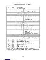
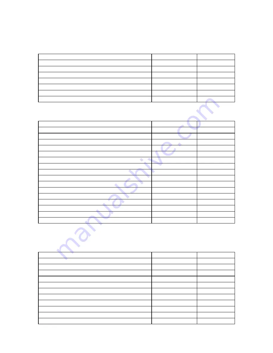
Data format of each error log structure is shown below.
Description
Bytes
Offset
1st command data structure
18
00h
2nd command data structure
18
12h
3rd command data structure
18
24h
4th command data structure
18
36h
5th command data structure
18
48h
Error data structure
34
5Ah
124
Figure 71 Extended Error log data structure
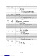
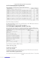
Command data structure:
Data format of each command data structure is shown below.
Description
Bytes
Offset
Device Control register
1
00h
Features register (7:0) (see Note)
1
01h
Features register (15:8)
1
02h
Sector count register (7:0)
1
03h
Sector count register (15:8)
1
04h
Sector number register (7:0)
1
05h
Sector number register (15:8)
1
06h
Cylinder Low register (7:0)
1
07h
Cylinder Low register (15:8)
1
08h
Cylinder High register (7:0)
1
09h
Cylinder High register (15:8)
1
0Ah
Device/Head register
1
0Bh
Command register
1
0Ch
Reserved
1
0Dh
Timestamp (milliseconds from Power-on)
4
0Eh
18
Note: bits (7:0) refer to the most recently written contents of the register. Bits (15:8) refer to the contents of the
register prior to the most recent write to the register.
Figure 72 Command data structure
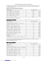
Error data structure: Data format of error data structure is shown below
.
Description
Bytes
Offset
Reserved
1
00h
Error register
1
01h
Sector count register (7:0) (see Note)
1
02h
Sector count register (15:8) (see Note)
1
03h
Sector number register (7:0)
1
04h
Sector number register (15:8)
1
05h
Cylinder Low register (7:0)
1
06h
Cylinder Low register (15:8)
1
07h
Cylinder High register (7:0)
1
08h
Cylinder High register (15:8)
1
09h
Device/Head register
1
0Ah