


27
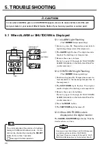
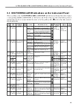
5. TROUBLESHOOTING [A List of SHUTDOWNS Not Displayed on Instrument Panel]
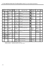
Readjust
Replace
Cleaning and refastening of Plumbing Equipments
Replace
Replace
Resetting
Replace with the appropriate one
Replace it with genuine synthetic oil (flashing inside is required.)
Check of Drain Suction Port and drainage
Flushing at Lubricant change
Disassemble/Repair
Replace
Refastening
Add some mortar to settle the foundation levelly
Adjust Belt Tension or replace it
Refastening
Add some mortar to settle the foundation levelly
Clean Fins
Clean
Clean drain discharge system then drain from under air cooler.
Adjust hot gas bypass valve to be 0.41 MPa or more.
Replace bypass valve if unadjustable.
Repair then fill refrigerant.
Keep ambient temperature below 40
°
C.
Clean cooler and replace fan.
Wash cycle then replace evaporator.
Adjust bypass valve to be the specified pressure.
Replace if unadjustable.
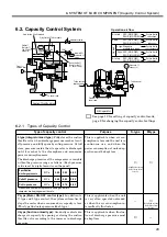
Capacity Control
malfunction
Lubricant
deterioration
too early
Strange noise from
the Main Body
Other unfamiliar
noises
Strange noise from Belt
Excessive Vibration
SYMPTOMS AND TROUBLES
POSSIBLE CAUSES
REMARKS
SOLUTIONS
*
Only for the 37 kW models.
**
Only if you installed an ammeter on the power supply.
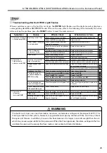
1. Running the unit with deteriorated lubricant unchanged or in a very hot condition brings the lubricant
ignites and this may cause serious accident.
Keep the lubricant well controlled (See pages 18 through 19).
2. Do not operate the unit without protective equipment. In case of SHUTDOWN, read this section “5.
TROUBLESHOOTING” to remove the cause. If the cause is unknown, inform and ask your dealer or
Hitachi Service Station.
WARNING
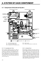
●
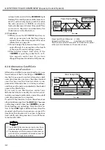
Running the unit with its loose belt brings not only lowered discharge air capacity due to its slipping,
but also life of belt shortened. If belt is broken during the operation, the lubricant blows out of the
Suction Throttle Valve. Be sure to carry out your constant check on belt.
●
If the unit stops due to the function of Temperature Relay, check leakage in the mechanical seal and
replace it if lubricant leak is found there.
CAUTION
Adjustment failure of Modulator Valve
Start Solenoid Valve* and/or Blow-off Solenoid Valve: Failed
Air-leak or clogging in plumbing system
Cap Seal damaged
Suction Throttle Valve’s rubber seat damaged or deformed
Inappropriate pressure setting
Use of other than genuine synthetic oil (NEW
A
OIL 2000)
Ambient Air Temperature too high
Water in the system
Deteriorated Lubricant still left
Compressor grips Foreign Particle
Inappropriate friction or damage of Bearing
Loose Bolts or Screws
Fault Installation
Belt slipping
Loose Bolts or Screws
Fault Installation
Unbalance of the unit due to Cooling Fan contamination
Drain trap clogging
Drain discharge system clogging
Air cooler frozen
Refrigerant leak
High intake air temperature
Noncondensing gas mixed in cycle
Hot gas bypass valve fault
Dryer fault
Refrigerant
pressure is low
but waterdrops
gather at outlet.
Refrigerant
pressure is high
and waterdrops
gather at outlet.
Содержание HISCREW 2000 Series
Страница 70: ...68 This page is intentionally blank ...