


-3-
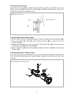
Fig. 3 • Removal of the O-ring
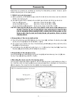
Fig. 4 • Disassembly of the retainer section
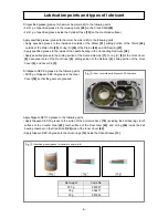
4. Removal of the O-rings
Because the two O-rings
[12]
are installed inside the Shank Sleeve
[13]
, it may be difficult to remove.
Gently pry the O-rings
[12]
upward with a small flat-blade screwdriver, while being very careful not to
damage the O-ring surface as illustrated in Fig. 3.
5. Disassembly of the striker section
(1) Remove the four Bolts M8 x 40
[23]
, and separate the Cylinder Case
[19]
from the Housing Ass’y
[49]
.
(2) Take out the Striker
[21]
, Piston
[26]
, and Connecting Rod Ass’y
[28]
in a single body from the
Cylinder Case
[19]
.
(3) Holding the Striker
[21]
firmly in one hand, grasp the Connecting Rod Ass’y
[28]
in the other hand and
pull it forcefully to separate it from the Striker
[21]
.
(4) Extract the Piston Pin
[25]
from the Piston
[26]
and separate the Piston Pin
[25]
from the Connecting
Rod Ass’y
[28]
.
6. Disassembly of the retainer section
Remove the two Roll Pins D6 x 55
[1]
from the 6 mm dia. holes of the Retainer
[2]
, and then remove the
Lever Pin
[3]
. The Retainer
[2]
and two Retainer Dampers (A)
[4]
can then be removed from the Front
Cover
[8]
.
.
[12]
[13]
Flat-blade screwdriver
[2]
[3]
[1]
[4]
[8]