background image

--- 4 ---

20

80

60

40

20

100  F

20

30

20

10

0

0

10

40  C

5W-30

10W-30

30

7. PRECAUTIONS IN SALES PROMOTION

In the interest of promoting the safest and most efficient use of the Models E 43, E 60 and E 71 Generators by all

of our customers, it is very important that at the time of sale the salesperson carefully ensures that the buyer

seriously recognizes the importance of the contents of the Handling Instructions, and fully understands the

meaning of the precautions listed on the Caution Plates attached to each unit.

7-1. Handling Instructions

Although every effort is made in each step of design, manufacture and inspection to provide protection against

safety hazards, the dangers inherent in the use of any generator cannot be completely eliminated.  Accordingly,

specific precautions and suggestions for the use of the generator are listed in the Handling Instructions to

enhance the safe and efficient use of the tool by the customer.  Salesperson must be thoroughly familiar with the

contents of the Handling Instructions to be able to offer appropriate guidance to the customer during sales

promotion.

7-2. Thorough Instruction to the Customers

(1) HITACHI electronic controlled products should not be used with portable generators.

Irregular generator power could cause these products to fail.  Regarding other manufacturer's products, please

contact the manufacturer to see if it is safe to use the electronic controlled products with portable generators.

(3) Each generator has AC receptacles as shown in the table below.

(2) There is no oil in the engine crankcase when the generator is shipped.  You must add oil before starting the

engine.  Check the oil level before each use with the generator on a level surface and the engine stopped.

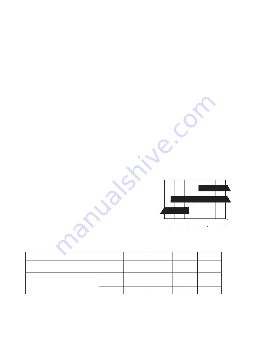
Engine oil is a major factor affecting engine performance and

service life.  Non-detergent and 2-stroke oils will damage the engine

and are not recommended.  Use 4-stroke motor oil that meets or

exceeds the requirements for API service classification SJ or SL.

Always check the API SERVICE label on the oil container to be sure

it includes the letters SJ or SL.  SAE 10W-30 is recommended for

general, all-temperature use.  Other viscosities shown in the right

graph may be used when the average temperature in your area is

within the indicated range.

Note that each of the above current values means the maximum current for one receptacle.

120 V

Output plug

Voltage

GFCI (Ground-fault circuit interrupter)
Duplex receptacles

Twist-locking receptacles

120 V

120/240 V

120/240 V

20 A

Current

30 A

20 A

30 A

2

E 43

1

1

None

2

E 60

2

None

1

2

E 71

2

None

1

Содержание E 71

Страница 1: ...DATA AND SERVICE MANUAL GENERATOR E 43 E 60 E 71 SPECIFICATIONS AND PARTS ARE SUBJECT TO CHANGE FOR IMPROVEMENT LIST Nos E 43 E027 E 60 E028 E 71 E029 August 2005 E MODELS E 43 E 60 E 71 Hitachi Power Tools E 60 ...

Страница 2: ... of Proper Generator 2 6 2 Starting Current 3 7 PRECAUTIONS IN SALES PROMOTION 4 7 1 Handling Instructions 4 7 2 Thorough Instruction to the Customers 4 8 MAINTENANCE 5 9 TROUBLESHOOTING GUIDE 6 9 1 Diagnosis and Corrective Action 6 9 2 Checking Continuity 18 9 3 Tightening Torque 20 9 4 Wiring Diagram 22 Assembly Diagram for E 43 Assembly Diagram for E 60 Assembly Diagram for E 71 ...

Страница 3: ...nd tools 4 SELLING POINTS 4 1 Selling Points Descriptions 1 Innovated design Each of the Models E 43 E 60 and E 71 is of a powerful and innovated design 2 Equipped with Honda s tried and true OHV GX engine Each of the Models E 43 E 60 and E 71 is equipped with Honda s tried and true OHV GX engine that is well reputed in the North American market Model E 43 The maximum output of the engine is 5 9 k...

Страница 4: ...525 157 71 198 90 181 82 223 101 201 91 243 110 50 0 25 0 6000 7100 6 CAPACITY OF GENERATOR 6 1 Selection of Proper Generator Select the proper generator as follows according to the power consumption output and the like of the AC electrical equipment to be used 1 When the power consumption of the electrical equipment is known When the power consumption of the electrical equipment is known calculat...

Страница 5: ...ion 3800 VA 5000 VA 6000 VA Generator Rated AC output E 43 E 60 E 71 Generally the following values are used though efficiency varies depending on the types of motors Motor output of the electrical equipment W Efficiency x Power factor Necessary output of the generator VA 6 2 Starting Current The current required from starting the above electrical equipment to operating in steady state is larger t...

Страница 6: ...uld not be used with portable generators Irregular generator power could cause these products to fail Regarding other manufacturer s products please contact the manufacturer to see if it is safe to use the electronic controlled products with portable generators 3 Each generator has AC receptacles as shown in the table below 2 There is no oil in the engine crankcase when the generator is shipped Yo...

Страница 7: ... remarkably and the electrical equipment will be overheated or put out of action To minimize voltage reduction it is necessary to use a short extension cord whose core is as thick as possible 5 Before operation perform inspection according to the Handling Instructions 8 MAINTENANCE Periodical maintenance is required for efficient use of the Models E 43 E 60 and E 71 by the customers Advise the cus...

Страница 8: ...ed in fuel The strainer is clogged The electrodes of the ignition plug are faulty The engine oil is highly viscous The air cleaner is clogged The carburetor is clogged Check and change the engine oil The throttle valve is closed due to improper adjustment of the governor Tighten the ignition plug Clean the ignition plug Adjust the clearance between the electrodes and replace the ignition plug if a...

Страница 9: ...rance between the electrodes is within the range from 0 028 to 0 031 inch from 0 7 to 0 8 mm Replace the ignition plug if there is any abnormality The ignition plug is stained or the clearance is improper Contact Honda Service Center The number of revolutions is abnormal increase decrease large variation Rated number of revolutions of the engine no load 3 400 to 3 800 r min reference The carbureto...

Страница 10: ...e is caused by any cause other than the above diagnose and take the necessary measures according to the following flow chart 1 Remove the Tapping Screw D5 x 10 6 and the End Cover 7 2 Remove the two couplers of the Wire Harness 162 white blue and yellow brown that connects the Stator 12 with the Panel Ass y 151 Do not remove the coupler of the Wire Harness 162 black black 3 Start the engine and ch...

Страница 11: ...ker 124 and the Thermal Protectors 117 119 1 Remove the three couplers of the Wire Harness 162 white blue yellow brown and black black that connects the Stator 12 with the Panel Ass y 151 and remove the Screw W Washer M5 x 12 13 2 Remove the Hex Bolt M6 x 24 77 from the side of the Panel Ass y 151 3 Pull the Panel Ass y 151 and remove the couplers of the Wire Harness 94 and the Wire Harness 161 fr...

Страница 12: ...crew W Washer M5 x 12 13 2 Remove the Hex Bolt M8 x 14 9 3 Remove the Through Bolt M6 x 120 10 Model E 43 M6 x 155 10 Model E 60 or M6 x 155 10 Model E 71 4 Remove the Hex Bolt M10 x 30 75 5 Remove the Rear Cover 11 6 Replace the Stator 12 Replace the Stator 12 v The field coil is broken Replace the Rotor Comp 3 1 Remove the three couplers of the Wire Harness 162 white blue yellow brown and black ...

Страница 13: ...l E 43 M10 x 215 2 Model E 60 or M10 x 260 2 Model E 71 without removing the Rotor Comp 3 from the Engine 71 8 Tighten the rotor puller bolt jig as a substitute for the Bolt M10 2 9 When the rotor puller bolt jig is tightened the tip of the jig contacts the crankshaft of the Engine 71 and a force is exerted to push out the Rotor Comp 3 from the Engine 71 10 Replace the Rotor Comp 3 CAUTION Do not ...

Страница 14: ...ve action Procedure It does not reach the rated voltage The number of revolutions of the Engine 71 is low Rated number of revolutions of the engine no load 3 400 to 3 800 r min reference Trouble If the trouble is caused by any cause other than the above diagnose and take the necessary measures according to the following flow chart 1 Remove the Tapping Screw D5 x 10 6 and the End Cover 7 2 Remove t...

Страница 15: ...oken or short circuited Replace the Stator 12 1 Remove the three couplers of the Wire Harness 162 white blue yellow brown and black black that connects the Stator 12 with the Panel Ass y 151 and remove the Screw W Washer M5 x 12 13 2 Remove the Hex Bolt M8 x 14 9 3 Remove the Through Bolt M6 x 120 10 Model E 43 M6 x 155 10 Model E 60 or M6 x 155 10 Model E 71 4 Remove the Hex Bolt M10 x 30 75 5 Re...

Страница 16: ...ith the Panel Ass y 151 and remove the Screw W Washer M5 x 12 13 2 Remove the Hex Bolt M8 x 14 9 3 Remove the Through Bolt M6 x 120 10 Model E 43 M6 x 155 10 Model E 60 or M6 x 155 10 Model E 71 4 Remove the Hex Bolt M10 x 30 75 5 Remove the Rear Cover 11 6 Replace the Stator 12 7 Remove the Bolt M10 x 215 2 Model E 43 M10 x 215 2 Model E 60 or M10 x 260 2 Model E 71 without removing the Rotor Com...

Страница 17: ...Wire Harness 162 white blue yellow brown and black black that connects the Stator 12 with the Panel Ass y 151 and remove the Screw W Washer M5 x 12 13 2 Remove the Hex Bolt M8 x 14 9 3 Remove the Through Bolt M6 x 120 10 Model E 43 M6 x 155 10 Model E 60 or M6 x 155 10 Model E 71 4 Remove the Hex Bolt M10 x 30 75 5 Remove the Rear Cover 11 6 Replace the Stator 12 Trouble The Condenser 145 is fault...

Страница 18: ...lt M8 x 14 9 3 Remove the Through Bolt M6 x 120 10 Model E 43 M6 x 155 10 Model E 60 or M6 x 155 10 Model E 71 4 Remove the Hex Bolt M10 x 30 75 5 Remove the Rear Cover 11 6 Replace the Stator 12 7 Remove the Bolt M10 x 215 2 Model E 43 M10 x 215 2 Model E 60 or M10 x 260 2 Model E 71 without removing the Rotor Comp 3 from the Engine 71 8 Tighten the rotor puller bolt jig as a substitute for the B...

Страница 19: ...ex Bolt M6 x 12 147 and open the Box Ass y 141 a little 6 Push the claws of the couplers above step 3 fitted in the Box Ass y 141 to remove the couplers from the Box Ass y 141 7 Remove the Grommet 144 and put the couplers above step 6 in the Box Ass y 141 8 Open the Box Ass y 141 and remove the Condenser 145 from the Wire Harness 162 9 Pull out the Wire Harness 162 from the Box Ass y 141 and remov...

Страница 20: ...tance at the coupler of the wire harness stator side when the generator is cold before operation Following are the resistance values measured at 20 ûC For 120 V 3 pole 118 Model E 43 1 pc Models E 60 and E 71 2 pcs For GFCI Ground Fault Circuit Interrupter 115 2 pcs Power receptacle Select Switch 125 E60 E71 E43 120 V side 240 V side 120 V side 240 V side 120 V side 240 V side There is no continui...

Страница 21: ... 19 Start of coil winding End of coil winding E60 Red line Start of coil winding End of coil winding E71 Red line Start of coil winding End of coil winding E43 ...

Страница 22: ...ty of the condenser E43 Bolt M10 x 215 2 E60 Bolt M10 x 215 2 E71 Bolt M10 x 260 2 Hex Bolt M10 x 40 83 Hex Nut M10 73 Hex Bolt M10 x 30 75 Hex Nut M10 73 Hex Bolt M8 x 14 9 Hex Bolt M8 x 18 4 Hex Bolt M8 x 18 68 Hex Bolt M8 x 20 Hex Bolt M8 x 18 63 Hex Bolt M8 x 14 82 Hex Bolt M8 x 14 82 Hex Bolt M8 x 18 63 Hex Bolt M8 x 18 63 Screw dia Location Tightening torque Fasteners Remark Quantity M10 M8 ...

Страница 23: ...er receptacle Twist lock 120 V 240 V 127 terminal Rectifier 122 Engine Air cleaner cover Power receptacle GFCI 115 Power Receptacle Twist lock 120 V 118 Breaker 124 Select Switch 125 Power Receptacle Twist lock 120 V 240 V 127 Thermal Protector 119 E43 Through Bolt M6 x 120 10 E60 Through Bolt M6 x 155 10 E71 Through Bolt M6 x 155 10 Hex Bolt M6 x 24 32 Hex Bolt M6 x 12 76 Hex Bolt M6 x 12 76 Hex ...

Страница 24: ...he Receptacle 127 Connect to the Wire Harness 162 Connect to the Receptacle 127 Connect one Thermal Protector 117 to the Breaker 124 Connect to the condenser Wire Harness 162 pulled out Put this wire through the hole Put this wire through the hole Hole Wire Harness pulled out 161 Cord Comp Gray 165 Cord Comp 168 Cord Comp Gray 172 Cord Comp Blue 171 Cord Comp Yellow 167 Cord Comp 163 Hole Cord Com...

Страница 25: ...127 Connect to the Wire Harness 162 Connect to the Power Receptacle 127 Connect one Thermal Protector 117 and one Terminal Protector 119 to the Breaker 124 Connect to the condenser Wire Harness 162 pulled out Put this wire through the hole Put this wire through the hole Hole Wire Harness 161 pulled out Cord Comp Gray 165 Cord Comp 168 Cord Comp Gray 172 Cord Comp Blue 171 Cord Comp Yellow 167 Cord...

Страница 26: ...ENGINE TOOL PARTS LIST LIST NO E027 GENERATOR Model E 43 2005 8 5 E1 Hitachi Power Tools GENERATOR TANK 40 9 41 1 2 3 4 5 6 7 9 8 13 10 11 12 32 33 34 32 33 34 36 37 38 39 39 35 31 ...

Страница 27: ...43 FRAME ACCESSORIES 75 74 76 61 63 67 62 63 65 63 64 65 66 63 64 68 85 94 77 78 79 80 81 82 82 73 73 73 74 75 84 89 90 91 72 91 90 89 92 63 82 90 89 93 A A 71 88 B B 74 73 76 83 73 70 73 95 61 62 64 66 93 91 84 ...

Страница 28: ...L BOX WIRE HARNESS 114 119 142 143 144 145 146 147 141 111 115 116 117 118 116 120 121 122 123 116 124 116 125 116 127 126 113 112 128 129 130 131 132 133 134 161 163 165 166 167 168 164 169 170 171 135 162 151 141 111 ...

Страница 29: ...5 TANK 1 36 683 727 FUEL VALVE 1 37 683 726 TANK CAP 1 38 683 728 FUEL FILTER 1 39 683 729 GROMMET 2 40 MARK PLATE H 1 41 683 800 TANK GAUGE 1 FRAME ACCESSORIES 61 683 754 HANDLE A COMP 1 62 683 753 HANDLE B COMP 1 63 683 758 HEX BOLT M8X18 8 64 683 750 HOOK STAY 2 65 683 755 HANDLE STAY CLAMP 2 66 683 749 HOOK COMP 1 67 683 744 FRAME B 1 68 683 743 HEX BOLT M8X18 4 70 683 740 TANK STAY 1 71 683 7...

Страница 30: ...3 689 IDLE CONTROL 1 121 683 700 HEX NUT 1 122 683 703 RECTIFIER 1 123 683 701 HEX NUT 1 124 683 787 BREAKER 1 125 683 691 SELECT SWITCH 1 126 683 705 PUSHING NUT 3 127 683 788 RECEPTACLE 1 128 MARK PLATE LU 1 129 MARK PLATE LD 1 130 683 697 SWITCH 2 131 MARK PLATE CE 1 132 MARK PLATE RU 1 133 MARK PLATE RD 1 134 683 698 WING NUT 1 135 683 797 MARK PLATE SET 1 INCLUD 112 128 129 131 133 BOX 141 68...

Страница 31: ...ATIVE PARTS 6 ITEM NO CODE NO DESCRIPTION REMARKS NO USED PARTS 8 05 E 43 Printed in Japan 050805N 168 683 716 CORD COMP 1 169 683 713 CORD COMP BLUE 1 170 683 717 CORD COMP BLUE 1 171 683 718 CORD COMP GRAY 1 ...

Страница 32: ...ENGINE TOOL PARTS LIST LIST NO E028 GENERATOR Model E 60 2005 8 5 E1 Hitachi Power Tools GENERATOR TANK 40 9 41 1 2 3 4 5 6 7 9 8 13 10 11 12 32 33 34 32 33 34 35 36 37 38 39 39 31 ...

Страница 33: ...60 FRAME ACCESSORIES 74 76 75 61 63 67 62 63 65 63 64 65 66 63 64 68 85 94 77 78 79 80 81 82 82 73 73 73 74 75 84 89 90 91 72 91 90 89 92 63 82 90 89 93 A A 71 88 B B 74 73 76 83 73 70 73 95 61 62 64 66 93 91 84 ...

Страница 34: ...BOX WIRE HARNESS 114 119 142 143 144 145 146 147 141 111 115 116 117 118 116 120 121 122 123 116 124 116 125 116 127 126 113 112 128 129 130 131 132 133 134 161 163 165 166 167 168 164 169 170 171 172 135 162 151 141 111 ...

Страница 35: ...5 TANK 1 36 683 727 FUEL VALVE 1 37 683 726 TANK CAP 1 38 683 728 FUEL FILTER 1 39 683 729 GROMMET 2 40 MARK PLATE H 1 41 683 800 TANK GAUGE 1 FRAME ACCESSORIES 61 683 754 HANDLE A COMP 1 62 683 753 HANDLE B COMP 1 63 683 758 HEX BOLT M8X18 8 64 683 750 HOOK STAY 2 65 683 755 HANDLE STAY CLAMP 2 66 683 749 HOOK COMP 1 67 683 744 FRAME B 1 68 683 743 HEX BOLT M8X18 4 70 683 740 TANK STAY 1 71 683 7...

Страница 36: ...689 IDLE CONTROL 1 121 683 700 HEX NUT 1 122 683 703 RECTIFIER 1 123 683 701 HEX NUT 1 124 683 690 BREAKER 1 125 683 691 SELECT SWITCH 1 126 683 705 PUSHING NUT 3 127 683 694 POWER RECEPTACLE 1 128 MARK PLATE LU 1 129 MARK PLATE LD 1 130 683 697 SWITCH 2 131 MARK PLATE CE 1 132 MARK PLATE RU 1 133 MARK PLATE RD 1 134 683 698 WING NUT 1 135 683 799 MARK PLATE SET 1 INCLUD 112 128 129 131 133 BOX 14...

Страница 37: ...TEM NO CODE NO DESCRIPTION REMARKS NO USED PARTS 8 05 E 60 Printed in Japan 050805N 168 683 716 CORD COMP 1 169 683 712 CORD COMP GRAY 1 170 683 713 CORD COMP BLUE 1 171 683 717 CORD COMP BLUE 1 172 683 718 CORD COMP GRAY 1 ...

Страница 38: ...ENGINE TOOL PARTS LIST LIST NO E029 GENERATOR Model E 71 2005 8 5 E1 Hitachi Power Tools GENERATOR TANK 40 9 41 1 2 3 4 5 6 7 9 8 13 10 11 12 32 33 34 32 33 34 36 37 38 39 39 35 31 ...

Страница 39: ...71 FRAME ACCESSORIES 75 74 76 61 63 67 62 63 65 63 64 65 66 63 64 68 85 94 77 78 79 80 81 82 82 73 73 73 74 75 84 89 90 91 72 91 90 89 92 63 82 90 89 93 A A 71 88 B B 74 73 76 83 73 70 73 95 61 62 64 66 93 91 84 ...

Страница 40: ...BOX WIRE HARNESS 114 119 142 143 144 145 146 147 141 111 115 116 117 118 116 120 121 122 123 116 124 116 125 116 127 126 113 112 128 129 130 131 132 133 134 161 163 165 166 167 168 164 169 170 171 172 135 162 151 141 111 ...

Страница 41: ...5 TANK 1 36 683 727 FUEL VALVE 1 37 683 726 TANK CAP 1 38 683 728 FUEL FILTER 1 39 683 729 GROMMET 2 40 MARK PLATE H 1 41 683 800 TANK GAUGE 1 FRAME ACCESSORIES 61 683 754 HANDLE A COMP 1 62 683 753 HANDLE B COMP 1 63 683 758 HEX BOLT M8X18 8 64 683 750 HOOK STAY 2 65 683 755 HANDLE STAY CLAMP 2 66 683 749 HOOK COMP 1 67 683 744 FRAME B 1 68 683 743 HEX BOLT M8X18 4 70 683 740 TANK STAY 1 71 683 7...

Страница 42: ...89 IDLE CONTROL 1 121 683 700 HEX NUT 1 122 683 703 RECTIFIER 1 123 683 701 HEX NUT 1 124 683 771 BREAKER 1 125 683 691 SELECT SWITCH 1 126 683 705 PUSHING NUT 3 127 683 694 POWER RECEPTACLE 1 128 MARK PLATE LU 1 129 MARK PLATE LD 1 130 683 697 SWITCH 2 131 MARK PLATE CE 1 132 MARK PLATE RU 1 133 MARK PLATE RD 1 134 683 698 WING NUT 1 135 683 798 MARK PLATE SET 1 INCLUD 112 128 129 131 133 BOX 141...

Страница 43: ...TEM NO CODE NO DESCRIPTION REMARKS NO USED PARTS 8 05 E 71 168 683 716 CORD COMP 1 169 683 712 CORD COMP GRAY 1 170 683 713 CORD COMP BLUE 1 171 683 717 CORD COMP BLUE 1 172 683 718 CORD COMP GRAY 1 Printed in Japan 050805N ...

Страница 44: ......

Отзывы: