26
Functional description of the circuits
The audio feature module AR700 consists only of a clock
oscillator, sound processor and delay memory.
The audio feature module AR701 consists of, in addition
to the above, a phase locked loop, reconstruction filtering,
D/A-converter and power amplifier.
Clock oscillator, icar1
The inverter circuit icar1 operates as a master clock oscil-
lator whose frequency of 25 MHz is determined by resistor
rar1 and capacitor car1. The clock pulses are output from
pin 8 to the sound processor pin 14.
Sound processor, icar2
The digital sound processor (DSP) includes several differ-
ent memories, namely a 512 x 32-bit program RAM, 256 x
24-bit data RAM, 256 x 24-bit coefficient RAM, 1.5 kilo word
x 32-bit program ROM and 1.5 kilo word x 24-bit coeffi-
cient ROM. In addition it includes a 24-bit arithmetic logic
unit (ALU) and 25-bit x 25-bit multiplier accumulator (MAC).
In addition the circuit includes a graphic equalizer, tone
control and noise generator.
The circuit is controlled by the IIC-bus. The control soft-
ware is stored in the program memory (ICf1), from which
it is sent to the microcontroller (icf3) and onward via the
IIC-bus to the sound processor. All presets are stored in
the NV RAM (ICf2). In order to ensure the proper function
of the IIC-bus during switch on and off, both the SDA and
SCL are taken to the sound processor via the +12 Vp volt-
age driven FETs, tar1 and tar2.
The DSP is connected to the MSP (ICa2) via the IIS-bus
which consists of four lines, data in (IIS-DI), data out (IIS-
DO), word select (IIS-WS) and clock (IIS-CLK). The word
select signal is a 32 kHz square wave pulse and it is used
for channel separation. The clock signal is a 1.024 MHz sine
wave pulse and is used as a system clock.
Delay memory, icar3
The delay memory is a 256 kbit (32k x 8) SRAM which to-
gether with the DSP is used to create the echoing effects
needed in the Dolby Pro Logic, 3D Mono and 3D Movie
systems.
Phase locked loop, icar4
The PLL circuit generates the master clock signal for the D/
A converter. The loop is locked to the IIS-WS signal (pin 1)
that operates as a 32 kHz system clock. The PLL multiplies
the 32 kHz signal by 384 resulting in the final master clock
signal of 12.288 MHz, output from pin 10.
Reconstruction filtering and D/A-conversion, icar5
and icar6
The reconstruction filtering and D/A-conversion is carried
out using two circuits, the D/A-converter with a digital fil-
ter, icar5 (TC9270), and the filter circuit, icar6 (TA2009F).
The TC9270 includes a serial input interface, de-emphasis,
interpolators, delta-sigma modulators and D/A-converters.
The audio data is input to pin 25, and output from pins 9 /
10 (surround) and 5 / 6 (center). The whole process is con-
trolled by three clock signals, the 1.024 MHz system clock
on pin 2, the 32 kHz word select signal on pin 3 and the
master clock on pin 4. Analog audio signals are then fed to
the lowpass filter circuit TAA2009, which performs the post
filtering. The surround channel is output from pin 6 and
center channel from pin 3 to the power amplifier.
Power amplifier, ICar7
The power amplifier used, TDA2616, is the same as that
used in the audio amplifier on the main board, and has
therefore already been covered in the Audio section.
The surround channel is output from pin 4 to the loud-
speaker connector Qar6. The impedance of the surround
speakers is 16 ohms, and thus they are connected in paral-
lel.
The center channel is output from pin 6 to the loudspeaker
connector Qar5 and to switch SWA1.
Loudspeaker selection switch, SWA1
This allows the TVs internal speakers to be used as a center
channel speaker. The internal speakers are connected to
connector Q4 and thus the signal route from the center
channel amplifier is SWA1 pins 15 / 14, connector pin 1 (+),
loudspeaker, connector pin 2 (-), connector pins 5 / 4 / 18 /
17, connector pin 3 (+), loudspeaker, connector pin 4 (-),
switch pins 2 / 1 and ground. Therefore, the internal speak-
ers are connected in series. The switch pins 1 / 2 drive the
sound processor via pin 27 to select the correct equaliza-
tion. In this loudspeaker configuration the left and right
channels must be connected to external speakers via loud-
speaker connectors Xexts1 and Xexts2 on the main board.
Power
amplifier
ICa1
Signal
processor
icar2
IIS-bus
Audio data
Delay memory
icar3
AR700
PLL
icar4
DAC
icar5
Reconst-
ruction
filter
icar6
Power
amplifier
ICar7
To surround
speakers
To external
center speaker
L&R / center
speaker switch
SWA1
To internal
speakers
IIC-bus
Control
Master
clock
icar1
L
R
Equalizer control
AR701
Mute
Reset
To external
L/R speakers
L
R
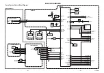
Block diagramme of the 3-audio (AR700) and 3D + Dolby Pro Logic module (AR701)
Содержание CP2896TA
Страница 84: ...21 DB700 710 Feature module ...
Страница 85: ...22 FC700 Control module ...
Страница 88: ...25 HH703 705 CRT module ...
Страница 93: ......
Страница 94: ......
Страница 95: ......
Страница 96: ......
Страница 97: ......
Страница 98: ......
Страница 99: ......
Страница 100: ......


