Analog Output Operation
In inverter applications it is useful to monitor
the inverter operation from a remote location or
from the front panel of an inverter enclosure. In
some cases, this requires only a panel-mounted
volt meter. In other cases, a controller such as a
PLC may provide the inverter’s frequency
command, and require inverter feedback data
(such as output frequency or output current) to
confirm actual operation. The analog output
terminal [AM] serves these purposes.
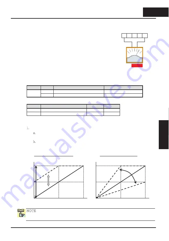
The inverter provides an analog voltage output on terminal [AM] with terminal [L] as
analog GND reference. The [AM] can output inverter frequency or current output value.
Note that the voltage range is 0 to +10V (positive-going only), regardless of forward or
reverse motor rotation. Use C028 to configure terminal [AM] as indicated below.
Func.
Code
Description
Range
00
Inverter output frequency
0 ~ Max. Frequency (Hz)
C028
01
Inverter output current
0 ~ 200% of rated current
The [AM] signal offset and gain are adjustable, as indicated below.
Func.
Description
Range
Default
B080
[AM] output gain adjustment
0.~255.
100.
C086
[AM] output offset adjustment
0.0~10.0
0.0
The graph below shows the effect of the gain and offset setting. To calibrate the [AM]
output for your application (analog meter), follow the steps below:
1. Run the motor at the full scale speed, or most common operating speed.
a. If the analog meter represents output frequency, adjust offset (C086) first, and
then use B080 to set the voltage for full scale output.
b. If [AM] represents motor current, adjust offset (C086) first, and then use B080 to
set the voltage for full scale output. Remember to leave room at the upper end of
the range for increased current when the motor is under heavier loads.
NOTE: As mentioned above, first adjust the offset, and then adjust the gain. Otherwise
the required performance cannot be obtained because of the parallel movement of the
offset adjustment.
AM H
O OI
L
+
-
A GND
Analog
Voltage
Output
10VDC
full scale,
1mA max
See I/O specs on page 4-6
Full scale (FS)
Hz or A
AM output
10V
0
1/2 FS
5V
B080=0~255
AM output gain adjustment
Full scale (FS)
Hz or A
AM output
10V
0
1/2 FS
5V
C086=0~10
Parallel
movement
AM output offset adjustment
4
57
Inverter Mounting
and i
n
st
all
ation
4
−
57
Operations and
Monitoring
Содержание CONVENTION 14
Страница 21: ......
Страница 83: ......
Страница 149: ......
Страница 184: ... this page is left intentionally blank 4 35 Operations and Monitoring 4 35 Operations and Monitoring ...
Страница 211: ......
Страница 219: ......
Страница 236: ...Glossary and Bibliography In This Appendix page Glossary 2 Bibliography 8 A A 1 Appendix A A 1 Appendix A ...
Страница 283: ......
Страница 293: ......
Страница 299: ......


