Front Housing Cover
HIGH VOLTAGE: Hazard of electrical shock. Disconnect incoming power before
working on this control. Wait five (5) minutes before removing the front cover.
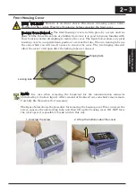
Housing Cover Removal – The front housing cover is held in place by a screw and two
pairs of tabs. Since these tabs are hidden from view, it is good to become familiar with
their locations
before attempting to remove the cover. The figure below shows a typical
housing cover in an upside-down position to reveal the tabs. The two locking tabs are
the ones which you will need to press to remove the cover. The two hinging tabs will
allow the cover to tilt open after the locking tabs are released.
NOTE: Use care when removing the knock-out for the communication connector
(indicated by A in above figure). After removal of the knock-out, some burrs may remain.
Carefully file them smooth, if necessary.
The figure below shows the procedure for removing the housing cover. First, unscrew the
screw, squeeze the side locking tabs, and then lift up the housing cover. DO NOT force
the cover open; it is possible to break a tab in this way.
2
3
Inverter Mounting
and i
n
st
all
atio
n
Hinging tabs
Locking tabs
A
1. Unscrew the screw
2. Lift up the bottom side of the cover
2
−
3
Inverter Mountingand
installation
Содержание CONVENTION 14
Страница 21: ......
Страница 83: ......
Страница 149: ......
Страница 184: ... this page is left intentionally blank 4 35 Operations and Monitoring 4 35 Operations and Monitoring ...
Страница 211: ......
Страница 219: ......
Страница 236: ...Glossary and Bibliography In This Appendix page Glossary 2 Bibliography 8 A A 1 Appendix A A 1 Appendix A ...
Страница 283: ......
Страница 293: ......
Страница 299: ......

