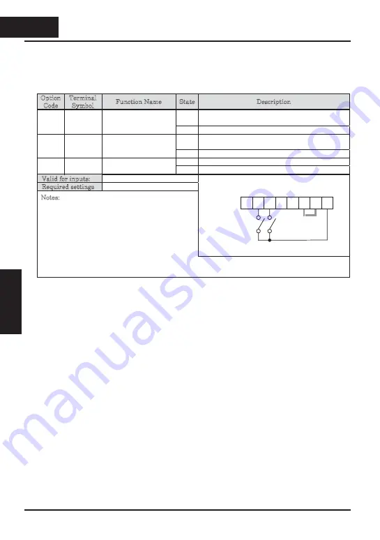
It is possible for the inverter to retain the frequency set from the
[
UP
]
and
[
DWN
]
terminals through a power loss. Parameter C101 enables/disables the memory. If
disabled, the inverter retains the last frequency before an UP/DWN adjustment. Use
the
[
UDC
]
terminal to clear the memory and return to the original set output frequency.
Option
Code
Terminal
Symbol
Function Name
State
Description
ON
Accelerates
(
increases output frequency
)
motor
from current frequency
27
UP
Remote Control UP
Function
(
motorized
speed pot.
)
OFF
Output to motor operates normally
ON
Decelerates
(
increases output frequency
)
motor
from current frequency
28
DWN
Remote Control
DOWN Function
(
motorized speed pot.
)
OFF
Output to motor operates normally
ON
Clears the Up/Down frequency memory
29
UDC
Remote Control Data
Clear
OFF
No effect on Up/Down memory
Valid for inputs
:
C001~C005
Required settings
A001 = 02
Notes
:
x
This feature is available only when the frequency
command source is programmed for operator
control. Confirm A001 is set to 02.
x
This function is not available when
[
JG
]
is in use.
x
The range of output frequency is 0 Hz to the value
in A004
(
maximum frequency setting
)
.
Example (default input configuration shown—see
page 3–49
):
See I/O specs on
page 4–6.
x
The minimum ON time of
[
UP
]
and
[
DWN
]
is 50 ms.
x
This setting modifies the inverter speed from using F001 output frequency setting as a starting point.
5
4
3
2
1
L
PCS P24
UP
DWN
4
28
4
−
28
Operations and
Monitoring
Содержание CONVENTION 14
Страница 21: ......
Страница 83: ......
Страница 149: ......
Страница 184: ... this page is left intentionally blank 4 35 Operations and Monitoring 4 35 Operations and Monitoring ...
Страница 211: ......
Страница 219: ......
Страница 236: ...Glossary and Bibliography In This Appendix page Glossary 2 Bibliography 8 A A 1 Appendix A A 1 Appendix A ...
Страница 283: ......
Страница 293: ......
Страница 299: ......


