-6-
III
II
0
I
2.0 mm (5/64”)
1.2 mm
(3/64”)
0.6 mm (1/32”)
20 mm (3/4
”)
1. Blade Movement
In the Model CJ 90VST, the orbital mechanism moves the blade up and down, and back and forward. The
amount of fore-and-aft blade movement can be adjusted by simply switching the change knob to any of the
four settings. The table below shows the modeled orbits of blade movement at each orbital position
(change knob position).
III
II
I
0
Orbit
al po
sition
Blade ed
ge mo
vem
ent
Perpendicular
movement only
2. Orbital Position Selection
Selecting the most appropriate orbital position for each cutting job is essential to achieve the best possible
cutting efficiency. However, as the best orbital position depends on workpiece hardness and thickness, the
desired finish of the cut surface, and other factors, setting a single, simple standard for selecting the best
orbital position is not practical. Table 1 below can be used as a general guide for the appropriate selection
of orbital position based on various factors.
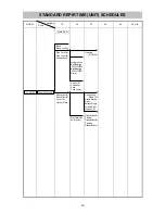
Table 1 General guide for appropriate selection of orbital position
Orbital position
Factor
III II I 0
Material hardness
Soft material
Hard material
Material thickness
Thick
Thin
Cutting speed
Faster cutting
Slower cutting
Straight cutting or
curved cutting
Straight cutting
Curved cutting
Surface finish
Rough finish acceptable
(splintering, chipping acceptable)
Fine finish
Material stability
Unstable
Very stable
* Set the orbital position to "0" independently of the cutting speed when cutting a small arc or curved line by
using a guide (sold separately).
ORBITAL MECHANISM AND BLADE


