background image

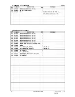
CJ 90VST

   DESCRIPTION

    REMARKS

501

879-357

JIG SAW BLADES NO. 41 (5 PCS.)

1

502

944-458

HEX. BAR WRENCH 4MM

1

*

503

332-420

CASE

1

EXCEPT FOR VEN, TPE, THA, INA, 

SIN, HKG, KUW, CHN, IND, LIB

   DESCRIPTION

    REMARKS

601

879-336

JIG SAW BLADES NO. 11 (5 PCS.)

1

602

879-337

JIG SAW BLADES NO. 12 (5 PCS.)

1

603

879-338

JIG SAW BLADES NO. 15 (5 PCS.)

1

604

879-339

JIG SAW BLADES NO. 16 (5 PCS.)

1

605

879-340

JIG SAW BLADES NO. 21 (5 PCS.)

1

606

879-341

JIG SAW BLADES NO. 22 (5 PCS.)

1

607

963-400

JIG SAW BLADES NO. 97 FOR STAINLESS (5PCS)

1

608

321-593

GUIDE

1

609

321-992

SUB BASE (A) SET (STEEL)

1

INCLUD. 611

610

321-993

SUB BASE (B) SET (PLASTIC)

1

INCLUD. 611

611

321-996

SPECIAL BOLT

4

612

321-591

DUST COLLECTOR

1

613

325-149

GREASE (MOLUB-ALLOY NO. 777-1) 75G

1

614

321-590

TABLE INSERT

1

- 4 -

Printed in Japan

6 - 10

                                        (100614N) 

          *ALTERNATIVE PARTS

STANDARD  ACCESSORIES

NO.

USED

CODE NO.

ITEM

NO.

NO.

USED

CODE NO.

ITEM

NO.

OPTIONAL ACCESSORIES

Содержание CJ 90VST

Страница 1: ...Model CJ 110MV by limiting its functions 1 Fastest cutting speed among jig saws using a high power motor 2 Blade holder of the quick fit chuck type with stronger blade holding force 3 4 stage orbital action With the features above the new jig saw will be released in order to increase its market share and sales MARKETING OBJECTIVE APPLICATIONS SELLING POINTS International Sales Division SPECIFICATI...

Страница 2: ...nual_view_export Throughout this TECHNICAL DATA AND SERVICE MANUAL a symbol s is are used in the place of company name s and model name s of our competitor s The symbol s utilized here is are as follows Competitors Symbols Utilized Company Name Model Name B BOSCH GST75BE C RYOBI EJS 600QEO D RYOBI JS550LK ...

Страница 3: ...ODUCTS 5 1 Comparison of Specifications 5 ORBITAL MECHANISM AND BLADE 6 1 Blade Movement 6 2 Orbital Position Selection 6 3 Blades 7 PRECAUTIONS ON SALES PROMOTION 8 1 Safety Instructions 8 REPAIR GUIDE 9 1 Precautions on Disassembly and Reassembly 9 STANDARD REPAIR TIME UNIT SCHEDULES 16 Assembly Diagram for CJ 90VST ...

Страница 4: ...150 200 CJ 90VST 187 HITACHI CJ 110MV 231 B 117 C 68 D 165 Material Wood 49 mm thick Blade No 41 Orbital position III Thrust power 2 0 kg Cutting speed cm min Maker Model 0 25 50 75 100 CJ 90VST 67 HITACHI CJ 110MV 85 B 65 C 16 D 55 Material Mild steel 2 mm thick Blade No 16 Orbital position 0 Thrust power 2 0 kg Cutting speed cm min Maker Model 0 10 20 30 40 50 CJ 90VST 44 HITACHI CJ 110MV 39 B 4...

Страница 5: ...ped with an orbital mechanism that allows the blade to move up and down and back and forward This mechanism allows the blade to cut deeply into wood and other soft materials and also discharges cutting chips well to achieve speedy cutting For details see Blade movement on page 6 Soft grip handle The handle of the Model CJ 90VST is completely covered with soft touch elastomer a rubber like soft res...

Страница 6: ...ft Type of motor Single phase AC commutator motor Insulation method Double insulation Type of switch Trigger switch Enclosure Housing Glass fiber reinforced nylon resin black and thermoplastic elastomer green Side cover Aluminum alloy die casting painted silver Base Aluminum alloy die casting Ni plated Net 2 2 kg 4 9 lbs without cord Weight Gross 3 5 kg 7 7 lbs with plastic case Overall length ove...

Страница 7: ...337 5 No 15 8 879338 5 Steel pulp nonferrous metal synthetic resin No 16 25 879339 5 No 21 6 879340 5 Wood pulp synthetic resin No 22 10 879341 5 Stainless steel No 97 21 963400 5 NOTE Standard blade No 41 and optional blade No 21 have the same shape 2 Guide Code No 321593 3 Sub base A steel Code No 321992 4 Sub base B resin Code No 321993 5 Dust collector Code No 321591 ...

Страница 8: ...rovided Provided Provided Provided Provided Tool less blade attachment Provided Provided Provided Provided Provided Soft grip handle Provided Provided Provided Provided Provided Material of base Aluminum Aluminum Steel plate Aluminum Resin plate Aluminum Steel plate Length A 228 mm 8 63 64 246 mm 9 41 64 232 mm 9 9 64 225 mm 8 55 64 238 mm 9 3 8 Height B 202 mm 7 61 64 206 mm 8 7 64 204 mm 8 1 32 ...

Страница 9: ...n workpiece hardness and thickness the desired finish of the cut surface and other factors setting a single simple standard for selecting the best orbital position is not practical Table 1 below can be used as a general guide for the appropriate selection of orbital position based on various factors Table 1 General guide for appropriate selection of orbital position Orbital position Factor III II ...

Страница 10: ...30 3 to 20 Mild steel plate 3 to 6 Below 3 2 to 5 1 5 to 8 Iron plate Stainless steel plate 1 5 to 2 5 Aluminum copper brass 3 to 12 Below 3 Below 5 Nonferrous metal Aluminum sash Height up to 25 Height up to 25 Height up to 30 Phenol resin melamin resin etc 5 to 20 Below 6 5 to 15 Below 6 5 to 15 Vinyl chloride acryl resin etc 5 to 30 Below 10 5 to 20 Below 5 5 to 30 3 to 20 5 to 15 Plastics Foam...

Страница 11: ...ent in the use of any electric tool cannot be completely eliminated Accordingly general precautions and suggestions on the use of electric power tools and specific precautions and suggestions on the use of the jig saw are listed in the Handling Instructions to enhance the safe efficient use of the tool by the customer Salespersons must be thoroughly familiar with the Handling Instructions in order...

Страница 12: ... the blade 1 Precautions on Disassembly and Reassembly Bold numbers in the descriptions below correspond to numbers in the Parts List and exploded assembly diagrams for the Model CJ 90VST 1 Disassembly of Base Loosen Hex Socket HD Bolt M5 X 16 69 and remove it together with Base Locker 68 from Plate Nut 64 mounted on Housing A B Set 36 2 Disassembly of Side Cover A Loosen two Tapping Screws W Flan...

Страница 13: ...g A B Set 1 Loosen eight Tapping Screws W Flange D4 X 20 Black 38 and open Housing A B Set 36 2 Loosen two Tapping Screws W Flange D4 X 16 49 disconnect Cord 56 and then remove Spring 13 Plate Nut 64 Roller Holder 46 Needle Roller 47 Brush Holder 32 and Carbon Brush 33 from Housing A B Set 36 The other half of Housing A B Set 36 can then be removed from the main body Disassembly of Housing A B Set...

Страница 14: ...Gear Holder Ass y 28 Disassembly of Gear Holder Assembly and Armature 4 Disassembly of Plunger Holder A and Blade Holder Assembly 1 Remove Plunger 15 Plunger Holder A 14 Plunger Holder B 16 and Packing 17 together 2 Loosen two Seal Lock Hex Socket HD Bolts M3 X 10 1 remove Blade Holder Ass y 2 and then pull out Packing 17 and Plunger Holder B 16 5 Disassembly of Gear Holder Assembly and Armature 1...

Страница 15: ... Ball D3 97 62 in Change Knob 60 as shown in the following diagram 2 Checking Insulator length Do not strip too much insulation from the end of each lead wire for connection Be careful not to let the lead wire be clamped by the joint of Housing A B Set 36 3 Other precautions 1 Make sure Earth Terminal 54 is completely inside Housing A B Set 36 before closing the set Otherwise the set will be defor...

Страница 16: ...D Bolt M5 X 16 69 3 43 to 6 37 N m 35 to 65 kgf cm Special Bolt M4 5 4 4 1 0 N m 45 10 kgf cm Machine Screw W Washer M3 5 X 6 42 0 6 0 15 N m 6 1 5 kgf cm Check the following after reassembly 1 Confirm normal switching operation of Switch E 1p Screw Type W Lock 41 2 Confirm that the stroke speed changes depending on the turning amount of Controller 43 3 Confirm that the blade can be attached secur...

Страница 17: ...er 43 Connector 50091 53 Switch E 1p Screw Type W Lock 41 Circuit diagram Carefully ensure that wiring is accomplished as illustrated below because incorrect wiring will result in inadequate or reverse rotation Wiring Diagram ...

Страница 18: ...er 43 Wiring diagram Connection to the switch Viewed from A with the varistor ass y Cord 56 white blue Terminal 45 red Varistor 50 white Terminal A M3 5 52 red Controller 43 red Cord 56 black brown Terminal 45 red Varistor 50 red Stator 35 gray Terminal 51 blue Controller 43 white blue ...

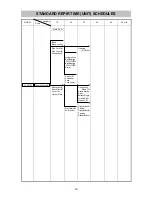
Страница 19: ... Holder B Lever A Holder Plate Armature Ass y Ball Bearing 608VVC2PS2L Ball Bearing 608VVC2PS2L Stator Switch E Controller Cord Cord Armor GearHolderAss y Roller Holder Housing A B Set Connecting Piece A Needle Bearing Gear Balance Weight Orbital Cam Washer A PlungerHolder A Plunger PlungerHolder B Packing BladeHolderAss y STANDARD REPIR TIME UNIT SCHEDULES ...

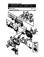
Страница 20: ...NO E525 E1 2010㨯6㨯14 1 4 13 16 17 14 15 18 20 21 23 24 25 26 27 28 29 30 31 32 33 34 35 39 40 38 37 36 43 47 50 42 49 45 51 54 52 53 44 41 55 56 59 57 58 61 62 60 67 66 65 64 69 68 501 502 503 63 46 3 10 9 8 5 6 7 12 11 2 22 19 48 ...

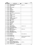
Страница 21: ...26 332 828 SPINDLE 1 27 998 426 NEEDLE ROLLER 1 28 332 444 GEAR HOLDER ASS Y 1 INCLUD 26 27 29 29 943 364 NEEDLE ROLLER D4 X 20 1 30 608 VVM BALL BEARING 608VVC2PS2L 1 31 360 893C ARMATURE 110V 1 31 360 893U ARMATURE ASS Y 120V 127V 1 INCLUD 30 34 31 360 893E ARMATURE 220V 240V 1 32 955 203 BRUSH HOLDER 2 33 999 041 CARBON BRUSH 1 PAIR 2 34 608 VVM BALL BEARING 608VVC2PS2L 1 35 340 773C STATOR 110...

Страница 22: ... CORD ARMOR D8 2 56 500 247Z CORD 1 CORD ARMOR D8 2 FOR FIN NOR SWE DEN 56 500 240Z CORD 1 CORD ARMOR D8 2 FOR USA CAN PAN 120V MEX 56 500 439Z CORD 1 CORD ARMOR D8 2 FOR NZL AUS 56 500 455Z CORD 1 CORD ARMOR D8 2 FOR THA CHN 56 500 450Z CORD 1 CORD ARMOR D8 2 FOR GBR 230V HKG 56 500 423Z CORD 1 CORD ARMOR D8 2 FOR SIN KUW 56 323 974 CORD 1 CORD ARMOR D10 2 FOR VEN TPE 56 500 461Z CORD 1 CORD ARMO...

Страница 23: ...LADES NO 16 5 PCS 1 605 879 340 JIG SAW BLADES NO 21 5 PCS 1 606 879 341 JIG SAW BLADES NO 22 5 PCS 1 607 963 400 JIG SAW BLADES NO 97 FOR STAINLESS 5PCS 1 608 321 593 GUIDE 1 609 321 992 SUB BASE A SET STEEL 1 INCLUD 611 610 321 993 SUB BASE B SET PLASTIC 1 INCLUD 611 611 321 996 SPECIAL BOLT 4 612 321 591 DUST COLLECTOR 1 613 325 149 GREASE MOLUB ALLOY NO 777 1 75G 1 614 321 590 TABLE INSERT 1 4...

Отзывы: