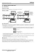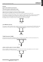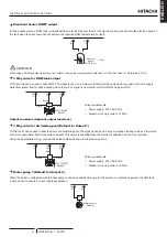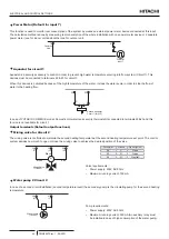
Power Meter (Default for input 7)
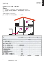
This function is used to monitor real consumption of the system by means an external power meter device connected at this input.
The calculation method is done by measuring real consumption of the whole installation with one power meter device or 2 separate
power meter (one for indoor unit and another one for outdoor unit.
Common
Line
Power M.
input 7
16
21
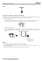
Aquastat for circuit 1
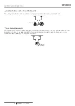
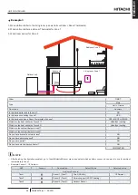
Aquastat is a security accessory to control in order to prevent high water temperature entering into floor system (Circuit 1). This
devices must be connected to terminals 22 & 23 for circuit 1.
When this devices is activated because of the high temperature of the water, it stops the water pump in order to stop the flow of
water to the heating floor.
22
23
C
Second Aquastat
1
Circuit 1 (for WP)
In case of YUTAKI S COMBI UK model, Domestic Hot water tank security thermostat its connected to terminals 22&23 and this
funcion is not available for circuit 1.
Output terminals (Default output functions)
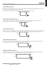
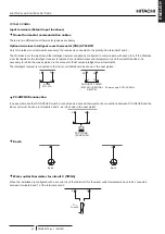
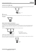
Mixing valve for Circuit 2
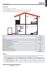
The mixing valve is controlled to maintain the second heating temperature at the second heating temperature set point. The control
system decides how much to open or close the mixing valve to achieve the desired position of the valve.
24
25
26
M
(C)
(O)
(N)
Brown
Black
Blue
Mixing Valve
(Circuit 2)
Terminal
Name
Description
24
C
Close
25
O
Open
26
N
Neutral
Valve requirements:
•
Power supply: 230V AC 50Hz
•
Maximum running current: 100mA
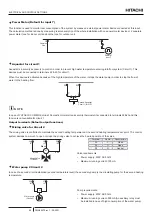
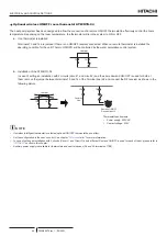
Water pump 2 Circuit 2
In case of a second circuit installation (second temperature level) the secondary pump is the circulating pump for the second heating
temperature.
26
(N)
M
27
(L)
Water pump II
(Circuit 2)
Pump requirements:
•
Power supply: 230V AC 50Hz
•
Maximum running current: 500mA (An auxiliary relay must
be installed in case of high consumption of the water pump).
ELECTRICAL AND CONTROL SETTINGS
PMML0575 rev.1 - 09/2021
46

