LC58/LC58E
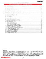
TO GO TO AN ADJUSTMENT, CLICK ON ITS HEADING BELOW
SERVICE ADJUSTMENTS
1.
CHASSIS
ADJUSTMENT.
........
............................................
.........
.....................................................................
32
1-1.
Service Menu Access
.....................
............................................................................................................................3
2
1-2. Memory Initialize ....................................................................................................................................
32
1-3.
Factory Reset ...........................................................................................................................................
33
1-4. Factory and Service Adjustments
...........................................................................................................
33
2. FINAL ASSEMBLY ADJUSTMENT (Adjustment order)
....................................................
..............................
33
2-1.
Preheat run conditions ............................................................................................................................33
2-2.
Subcontrast Adjustment .........................................................................................................................
33
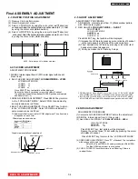
2-3.
Raster Position Adjustment ....................................................................................................................
34
2-4.
Flicker Adjustment
..................................................................................................................................
34
2-5.
Ghost Adjustment
...................................................................................................................................34
2-6.
NRSH Adjustment
..................................................................................................................................34
2-7.
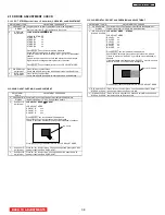
Display Area Specifications ....................................................................................................................35
2-8.
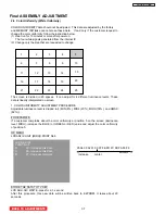
Gamma Correction (White Balance)
.........
...............................................................
............................3
6
2-
9
.
Color Uniformity (White Uniformity)
....................................................................................................3
7
2-1
0. Drive Adjustment Check
.......................................................................................................................3
8
2-10-1. Dot Stripe Checking ...................................................................................................................38
2-10-2. Sub Ghost Checking ..................................................................................................................38
2-1
0-3. Horizontal Crosstalk Checking ...................................................................................................38
2-11. Lamp Door Protection Operation Check
...............................................................................................39
2-1
2
.
Lamp Holder Protection Operation Check
.
..........................................................................................39
2-1
3.
High Temperature Protection Operation Check ....................................................................................39
2-1
4.
Temperature Sensor Data Setting
.......................................................................................................40
2-1
5.
Checking of Temperature Sensor
.
........................................................................................................4
1
2-1
6.
Adjustment I
2
C Parameter List
..............................................................................................................4
2
2-1
7
.
Adjustment OSD Flow Chart
.
.................................................................................................................79
2-1
8
.
Troubleshooting Flow Charts
.............................................................................................................................88
*IMPORTANT
For many of the above adjustments, it is necessary to have an HDTV (1080i or 720P) signal generator, SDTV (480P)
signal generator, as well as the usual NTSC (480i) signal generator.
Hitachi recognizes that few companies offer HDTV or SDTV signal generators and that the cost of these generators is
sometimes prohibitive. For this reason, we suggest the use of a set-top-box for HDTV and SDTV adjustments. Usually,
there is a switch on the set-top-box which enables it to output HDTV (1080i or 720P) or SDTV (480P) signals even with
no input. In this case, the sync is automatically detected by the TV (at the Y-P
B
P
R
Inputs on the rear panel).
TABLE OF CONTENTS
31
Содержание 50VF820 - 50" Rear Projection TV
Страница 96: ...LC58 LC58E CIRCUIT BLOCK DIAGRAM TABLE OF CONTENTS 96 ...
Страница 97: ...LC58 LC58E POWER SUPPLY BLOCK DIAGRAM TABLE OF CONTENTS 97 ...
Страница 98: ...CONNECTION DIAGRAM TABLE OF CONTENTS LC58 LC58E 98 ...
Страница 105: ...LC58 chassis Model 50VF820 55VF820 60VF820 1 FRONT PANEL 2 REAR PANEL LC58 LC58E 105 ...
Страница 106: ...LC58E chassis Model 50VG825 55VG825 60VG825 1 FRONT PANEL 2 REAR PANEL LC58 LC58E 106 ...
Страница 110: ...TABLE OF CONTENTS FINAL WIRING DIAGRAM TABLE OF CONTENTS TABLE OF CONTENTS LC58 LC58E 110 Model 55VF820 Model 55VG825 ...
Страница 125: ...LC58 LC58E WAVEFORMS AT EACH SECTION PST Pin 63 SDA PST Pin 64 SCL 25 26 Click on number to go to schematic 125 ...
Страница 155: ...SIGNAL PWB Solder side PRINTED CIRCUIT BOARDS BACK TO TABLE OF CONTENTS LC58 LC58E 155 ...
Страница 159: ...PRINTED CIRCUIT BOARDS POWER PWB Solder side BACK TO TABLE OF CONTENTS LC58 LC58E 159 ...
Страница 162: ...PRINTED CIRCUIT BOARDS DOOR SW A PWB Component side Solder side BACK TO TABLE OF CONTENTS LC58 LC58E 162 ...
Страница 163: ...PRINTED CIRCUIT BOARDS DOOR SW B PWB Component side Solder side BACK TO TABLE OF CONTENTS LC58 LC58E 163 ...
Страница 167: ...PRINTED CIRCUIT BOARDS PJIG A PWB Solder side BACK TO TABLE OF CONTENTS LC58 LC58E Component side 167 ...
Страница 168: ...PRINTED CIRCUIT BOARDS PJIG C PWB BACK TO TABLE OF CONTENTS LC58 LC58E Solder side Component side IJC1 IC 168 ...
Страница 169: ...PRINTED CIRCUIT BOARDS TACT SW PWB BACK TO TABLE OF CONTENTS LC58 LC58E Component side Solder side 169 ...
Страница 190: ......

