


Many electrical and mechanical parts in HITACHI television
receivers have special safety-related characteristics. These are
often not evident from visual inspection nor can the protection
afforded by them necessarily be obtained by using replacement
components rated for higher voltage, wattage, etc. Replacement
parts which have these special safety characteristics are identified
in this Service Manual.
Electrical components having such features are identified with an
!
mark in the schematics and parts list in this Service Manual.
The use of a substitute replacement component which does not
have the same safety characteristics as the HITACHI-recom-
mended replacement component, shown in the parts list in this
Service Manual, may create shock, fire, or other hazards.
Production safety is continuously under review and new instruc-
tions are issued from time to time. For the latest information,
always consult the current HITACHI Service Manual. A subscrip-
tion to, or additional copies of HITACHI Service Manuals may be
obtained at a nominal charge from HITACHI Sales Corporation.
Ultraviolet Radiation
OPTIC UNIT:
The primary source of Ultraviolet Radiation in this
receiver is the optic unit. The optic unit utilized in this chassis is
specially constructed to limit Ultraviolet Radiation emissions. For
continued Ultraviolet Radiation protection, the replacement optic
unit must be the same type as the original HITACHI-approved
type.
Service Personnel - WARNING
Eye damage may result from directly viewing the light produced by
the lamp used in this product. Always turn off lamp before open-
ing optic unit. Ultraviolet radiation eye protection required during
servicing.
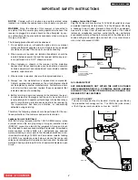
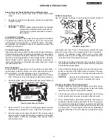
When troubleshooting and making test measurements in a receiv-
er with an excessive high voltage problem, avoid being unneces-
sarily close to the optic unit and the high voltage component.
Do not operate the chassis longer than is necessary to locate the
cause of excessive voltage.
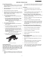
This Service Manual is intended for qualified service techni-
cians; it is not meant for the casual do-it-yourselfer. Qualified
technicians have the necessary test equipment and tools, and
have been trained to properly and safely repair complex prod-
ucts such as those covered by this manual. Improperly per-
formed repairs can adversely affect the safety and reliability of
the product and may void warranty. Consumers should not risk
trying to do the necessary repairs and should refer to a quali-
fied service technician.
WARNING
Lead in solder used in this product is listed by the California Health
and Welfare agency as a known reproductive toxicant which may
cause birth defects or other reproductive harm (California Health
and Safety Code, Section 25249.5).
When servicing or handling circuit boards and other compo-
nents which contain lead in solder, avoid unprotected skin
contact with solder. Also, when soldering do not inhale any
smoke or fumes produced.
SAFETY NOTICE
USE ISOLATION TRANSFORMER
WHEN SERVICING
Components having special safety characteristics identi-
fied by
!
on the parts list in this service manual and its
supplements and bulletins. Before servicing this product, it
is important that the service technician read and follow the
“Safety Precautions” and the “Product Safety Notices” in
this Service Manual.
For continued ultraviolet protection, replace optic unit with
original type or HITACHI equivalent type.
POWER SOURCE
This television receiver is designed to operate on 120
Volts/60Hz, AC house current. Insert the power cord into
a 120 Volts/60Hz outlet.
NEVER CONNECT THE TV TO OTHER THAN THE
SPECIFIED VOLTAGE OR TO DIRECT CURRENT.
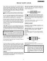
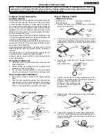
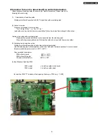
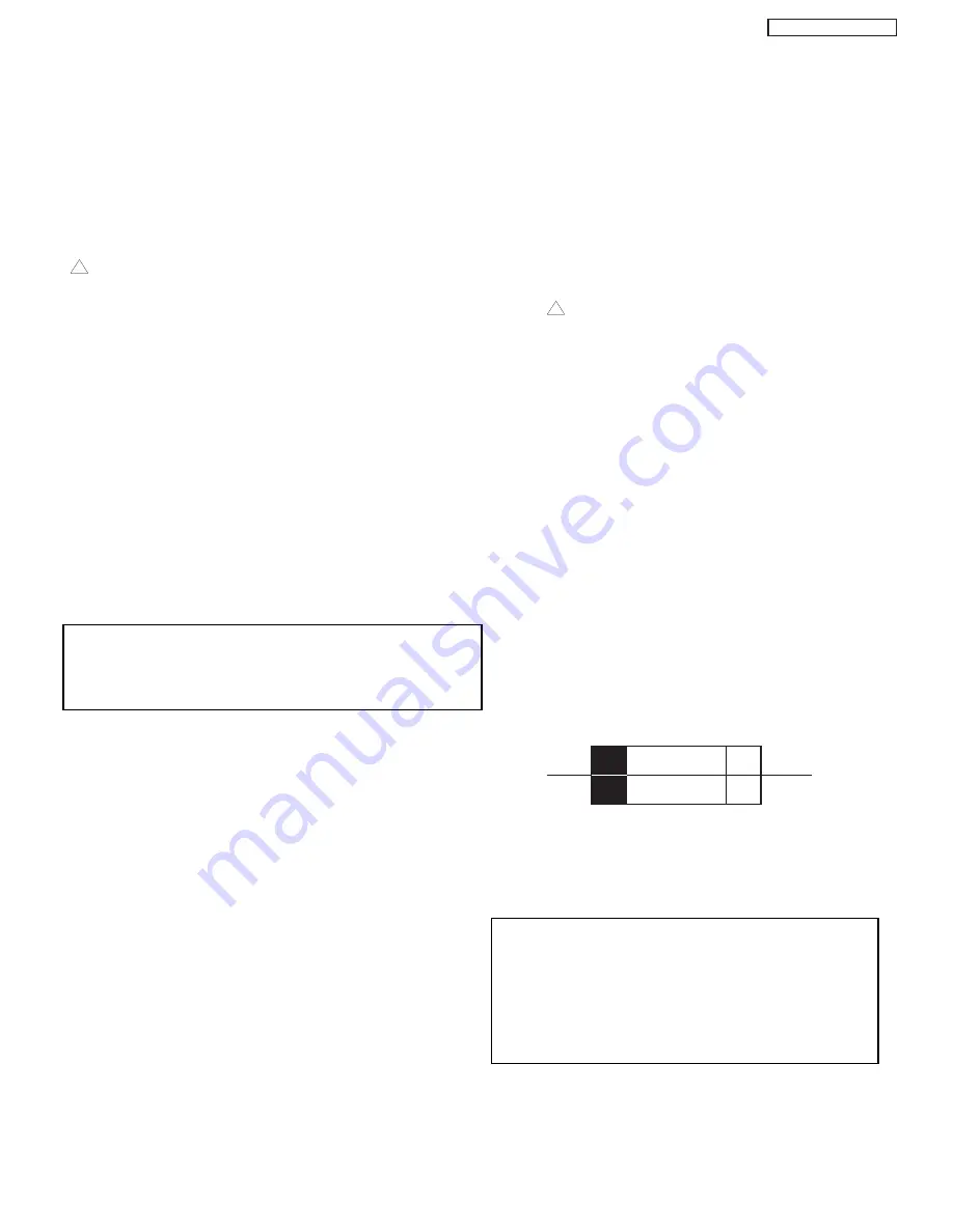
CAUTION!
The following symbol near the fuse indicates fast operat-
ing fuse (to be replaced). Fuse ratings appear within the
symbol.
Example:
The rating of fuse F101 is 6.0A-125V.
Replace with the same type of fuse for continued protec-
tion against fire.
The lamp in this product contains Mercury.
Dispose of properly in accordance with applicable
environmental laws. For Recycling and Disposal
information, contact your respective governmen-
tal agencies or the Electronic Industries Alliance
at www.eiae.org (in the U.S.) or Electronic
Product Stewardship Canada at www.epsc.ca (in
Canada).
PRODUCT SAFETY NOTICE
125V
6A
F901
NOTE:
F101
LC58/LC58E
3
Содержание 50VF820 - 50" Rear Projection TV
Страница 96: ...LC58 LC58E CIRCUIT BLOCK DIAGRAM TABLE OF CONTENTS 96 ...
Страница 97: ...LC58 LC58E POWER SUPPLY BLOCK DIAGRAM TABLE OF CONTENTS 97 ...
Страница 98: ...CONNECTION DIAGRAM TABLE OF CONTENTS LC58 LC58E 98 ...
Страница 105: ...LC58 chassis Model 50VF820 55VF820 60VF820 1 FRONT PANEL 2 REAR PANEL LC58 LC58E 105 ...
Страница 106: ...LC58E chassis Model 50VG825 55VG825 60VG825 1 FRONT PANEL 2 REAR PANEL LC58 LC58E 106 ...
Страница 110: ...TABLE OF CONTENTS FINAL WIRING DIAGRAM TABLE OF CONTENTS TABLE OF CONTENTS LC58 LC58E 110 Model 55VF820 Model 55VG825 ...
Страница 125: ...LC58 LC58E WAVEFORMS AT EACH SECTION PST Pin 63 SDA PST Pin 64 SCL 25 26 Click on number to go to schematic 125 ...
Страница 155: ...SIGNAL PWB Solder side PRINTED CIRCUIT BOARDS BACK TO TABLE OF CONTENTS LC58 LC58E 155 ...
Страница 159: ...PRINTED CIRCUIT BOARDS POWER PWB Solder side BACK TO TABLE OF CONTENTS LC58 LC58E 159 ...
Страница 162: ...PRINTED CIRCUIT BOARDS DOOR SW A PWB Component side Solder side BACK TO TABLE OF CONTENTS LC58 LC58E 162 ...
Страница 163: ...PRINTED CIRCUIT BOARDS DOOR SW B PWB Component side Solder side BACK TO TABLE OF CONTENTS LC58 LC58E 163 ...
Страница 167: ...PRINTED CIRCUIT BOARDS PJIG A PWB Solder side BACK TO TABLE OF CONTENTS LC58 LC58E Component side 167 ...
Страница 168: ...PRINTED CIRCUIT BOARDS PJIG C PWB BACK TO TABLE OF CONTENTS LC58 LC58E Solder side Component side IJC1 IC 168 ...
Страница 169: ...PRINTED CIRCUIT BOARDS TACT SW PWB BACK TO TABLE OF CONTENTS LC58 LC58E Component side Solder side 169 ...
Страница 190: ......


