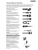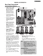
TV AS CENTER (INPUTS 1-4)
These jacks are for stereo amplifiers with center
signal output capability. This feature allows the TV
speakers to be used as a center speaker. The TV
must be set as a center channel by selecting
TV
AS CENTER
on the Internal Speakers Settings of
the Audio Menu.
CableCARD Slot
This slot is for the CableCARD that will be provided
by your local cable operator to gain access to
chosen cable channels. The CableCARD will allow
you to tune digital and high definition cable
channels. Please call your local cable operator if
this service is available before requesting a
CableCARD (also known as Point of Deployment
(POD) module).
1.
Connect a coaxial cable to cable terminal of
the Rear Panel Jacks.
2.
Insert the CableCARD into the slot (Top of card
should be facing right as shown below).
NOTE:
1. A digital cable subscription is required.
2. Do not insert a PCMCIA card into the
CableCARD slot.
If the CableCARD is properly installed or not installed,
the TV will display the following respective screens.
After the CableCARD is installed, wait until the second
screen below appears. The third screen below will
appear if a channel is not authorized for viewing. Press
the
EXIT
button to exit the second screen.
Please take note of all information on the screen (you
will provide this information to your cable operator).
Call your cable operator and give them the information
from the card to start your cable service.
Not an
A
uthorized Channel
In order to start cable service
for this device, please contact
your cable provider
CableC
A
RD(tm): 12
3
-456-789-1
Host: 12
3
-456-789-1
Data: 12
3
-456-789-1
Unit
A
ddress: 12
3
-456-789-1
Press EXIT to return
A
cquiring Data.
Please
w
ait.
OR
OR
CableCARD is not installed
CableCARD is installed
Rear Panel Connections
R
L
A
U
D
I
O
V
I
D
E
O
S
I
V
I
D
E
O
(MONO)
(MONO)
(MONO)
(MONO)
P
R
P
B
Y/
VIDEO
Y/
VIDEO
P
R
P
B
P
R
P
B
P
R
P
B
MONITOR OUT
AUDIO
TO HI-FI
INPUT 1
CABLE
AIR
INPUT 2
TV AS CENTER
INPUT 3 INPUT 4
CableCARD™
CAUTION
(Top of card faces right)
Top faces
OPTICAL OUT
Digital Audio
Upgrade Card
HDMI INPUT 1
Apparatu
s
Claim
s
of U.
S
.
Patent No
s
. 4,631,603;
4,577,216; 4,819,098;
4,907,093; and 6,381,747
licen
s
ed for limited
viewing u
s
e
s
only.
Digital Cable
CableCARD™
Top faces this
way
HDMI INPUT 2
LC58/LC58E
GENERAL INFORMATION
20
Содержание 50VF820 - 50" Rear Projection TV
Страница 96: ...LC58 LC58E CIRCUIT BLOCK DIAGRAM TABLE OF CONTENTS 96 ...
Страница 97: ...LC58 LC58E POWER SUPPLY BLOCK DIAGRAM TABLE OF CONTENTS 97 ...
Страница 98: ...CONNECTION DIAGRAM TABLE OF CONTENTS LC58 LC58E 98 ...
Страница 105: ...LC58 chassis Model 50VF820 55VF820 60VF820 1 FRONT PANEL 2 REAR PANEL LC58 LC58E 105 ...
Страница 106: ...LC58E chassis Model 50VG825 55VG825 60VG825 1 FRONT PANEL 2 REAR PANEL LC58 LC58E 106 ...
Страница 110: ...TABLE OF CONTENTS FINAL WIRING DIAGRAM TABLE OF CONTENTS TABLE OF CONTENTS LC58 LC58E 110 Model 55VF820 Model 55VG825 ...
Страница 125: ...LC58 LC58E WAVEFORMS AT EACH SECTION PST Pin 63 SDA PST Pin 64 SCL 25 26 Click on number to go to schematic 125 ...
Страница 155: ...SIGNAL PWB Solder side PRINTED CIRCUIT BOARDS BACK TO TABLE OF CONTENTS LC58 LC58E 155 ...
Страница 159: ...PRINTED CIRCUIT BOARDS POWER PWB Solder side BACK TO TABLE OF CONTENTS LC58 LC58E 159 ...
Страница 162: ...PRINTED CIRCUIT BOARDS DOOR SW A PWB Component side Solder side BACK TO TABLE OF CONTENTS LC58 LC58E 162 ...
Страница 163: ...PRINTED CIRCUIT BOARDS DOOR SW B PWB Component side Solder side BACK TO TABLE OF CONTENTS LC58 LC58E 163 ...
Страница 167: ...PRINTED CIRCUIT BOARDS PJIG A PWB Solder side BACK TO TABLE OF CONTENTS LC58 LC58E Component side 167 ...
Страница 168: ...PRINTED CIRCUIT BOARDS PJIG C PWB BACK TO TABLE OF CONTENTS LC58 LC58E Solder side Component side IJC1 IC 168 ...
Страница 169: ...PRINTED CIRCUIT BOARDS TACT SW PWB BACK TO TABLE OF CONTENTS LC58 LC58E Component side Solder side 169 ...
Страница 190: ......

