background image

Chapter 4: Software Interface 


Exicor MicroImager User Manual 


27 

Offsets 

The offset button is found just below the sample button. Clicking this button will take 
map the current retardation and angle of the image and then store it in memory to be 
subtracted later.  

After you take an offset, you can choose to use the offset or not by checking the box 
next to the offset button. 

Each color/objective combination will have its own unique offset. For example, if you 
create an offset for a 2x objective using the red LED, you will only be able to use that 
offset when the software is set to the red LED and the 2x objective. 


Display of data 

Data is displayed in 7 Different formats. Intensity, Retardance, Angle, Retardance 
and Angle, Retardance and Intensity, Angle and Intensity, and all three together.  

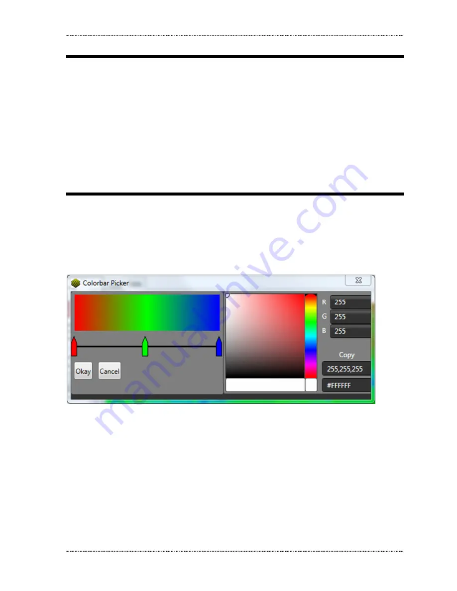
When displaying single sets of data the color map in the upper right corner provides 
the legend to change the color scheme of the image. Clicking on the color map 
brings up the screen shown in Figure 11. 


Figure 11 Colorbar Picker. 

To change between preset color configurations, such as grayscale, right click on the 
left colored part and choose the color scheme desired.  

To create a custom color scheme, you can add colors by clicking on the slider bar. 
To choose what color you want a particular marker to be, click on it and then move 
the selector in the hue generator to pick the color you would like. 

To choose the maximum and minimum values of the color map, it is possible to 
either use an auto setting by clicking the Auto max/min or Full max/min buttons on 
the right side of the screen or setting custom values. Auto max/min will use the 
pixels with the lowest and highest values to determine the maximum and minimum. 

Содержание EXICOR MicroImager

Страница 1: ...USER MANUAL Hinds Instruments Inc P N 010 0000 077 UM Rev D Software 025 0000 075 Beta Version ...

Страница 2: ...nstruments Inc Information furnished by Hinds Instruments Inc is believed to be accurate and reliable however no responsibility is assumed by Hinds Instruments Inc for its use nor for any infringements of patents or other rights of third parties which may result from its use No license is granted by implication or otherwise under any patent rights of Hinds Instruments Inc In all respects the Engli...

Страница 3: ...tions 17 Calibration 17 3 Operating The System 19 System Initialization 19 Loading a Sample 20 Measuring a Sample 21 System Shutdown 22 4 Software Interface 24 Calibration 24 Opening Files 24 Setting Exposure 25 Changing Objectives 26 Fast Mode 26 Offsets 27 Display of data 27 Analysis 28 Multi Order Samples 31 Auto Collect 32 5 Calibration 35 Calibration Procedure 35 6 Maintenance 48 Basic System...

Страница 4: ...Table of Contents iv Exicor MicroImager User Manual Software Features 53 CE Approval 53 B Exicor MicroImager Limited Warranty 55 Exclusions 55 Warranty Service 55 Non Warranty Repairs 56 ...

Страница 5: ... Figure 8 Completed scan 22 Figure 9 Over exposure Live Screen 25 Figure 10 Overexposure Data Screen 26 Figure 11 Colorbar Picker 27 Figure 12 Analysis Toolbar 28 Figure 13 Shape Tool Examples 29 Figure 14 Shape Tool Options 30 Figure 15 Dataset Tab 31 Figure 16 Datasets Window 32 Figure 17 Auto Collect Main Window 33 Figure 18 Auto Collect Start Window 33 Figure 19 Auto Collect Status Window 34 F...

Страница 6: ...Table of Figures vi Exicor MicroImager User Manual 45 Figure 10 45 Figure 11 46 Table 2 Diagnosing common errors 50 Table 3 Contacting technical support 51 ...

Страница 7: ...r Safety Summary Exicor MicroImager User Manual vii Table of Tables Table 01 Software to Rotator Readings Error Bookmark not defined Table 2 Diagnosing common errors 50 Table 3 Contacting technical support 51 ...

Страница 8: ...Table of Tables viii Exicor MicroImager User Manual ...

Страница 9: ... result in damage to the equipment or other property NOTICE statements identify conditions or practices that are important in proper use of the equipment to get the expected results Labels The system identification label below is placed on the rear of the MicroImager frame Figure 1 System identification label The wording on this label is Model No _____ Serial No _____ Manufactured _____ Power Sour...

Страница 10: ...te without Covers To avoid personal injury only operate this product with all covers and panels installed Light Safety The light source is located in the bottom module of the system It is a 3 wavelength LED that outputs 1mW Removing any covers all of them require tools can expose a user to the LED light The light beam path is shown in Figure 2 CAUTION Avoid direct eye exposure to the beam and to r...

Страница 11: ...afety Rear panel outlets other than the DC input are only USB 3 0 connectors which do not exceed 5 Volts The Exicor MicroImager contains no user serviceable components Refer any maintenance or adjustment needs to Hinds Instruments Inc Do not allow any liquids to get inside the equipment Maintenance of the other elements of the system should be referred to Hinds Instruments Inc or other trained per...

Страница 12: ...Electrical Safety 12 Exicor MicroImager User Manual ...

Страница 13: ...th fine and coarse adjustment knobs Use the larger outer knob to adjust the coarse focus and the smaller inner knob to adjust the fine focus Bottom Module The Bottom Module houses the electronics of the system as well as the bottom half of the optical train of the system The bottom half also houses the light source Sample Stage The Sample Stage can be moved in the vertical direction by the focus b...

Страница 14: ...System Description 14 Exicor MicroImager User Manual Figure 3 System main components Figure 4 Main optical components of the system LED PEM 45 POLARIZER 0 CUSTOMER SAMPLE PEM 0 CCD POLARIZER ...

Страница 15: ...Chapter 1 System Overview Exicor MicroImager User Manual 15 General Dimensions Figure 5 Dimensions ...

Страница 16: ...General Dimensions 16 Exicor MicroImager User Manual ...

Страница 17: ...VDC while accepting 100 240VAC 50 60 Hz User adjustment should not be necessary for any internal components due to changes in power The Exicor MicroImager system requires a single power outlet The computer and monitor need to be powered separately from a user supplied wall outlet or outlet strip Calibration The Exicor MicroImager has been calibrated by Hinds Instruments Inc prior to shipment The i...

Страница 18: ...Calibration 18 Exicor MicroImager User Manual ...

Страница 19: ... section beginning on page vii System Initialization To initialize the Exicor MicroImager system starting with the power off 1 Turn the power switch to the ON position The power switch is found on the rear panel of the machine 2 Launch the software by double clicking on the Exicor desktop icon During hardware initialization the user might notice the LED and camera will initialize using the setting...

Страница 20: ...o get reproducible measurements is to make a custom sample holder that holds the sample and fastens to the stage in a repeatable way Hinds Instruments can also supply custom sample holders as an option Use the following steps to load a sample 1 Place the sample on the stage Do not hold the sample to the stage in a way that might put stress on the sample 2 Using the manual adjusters move the sample...

Страница 21: ...suring a Sample 1 Choose the color of light desired by clicking the corresponding checkbox 2 Choose the Objective setting corresponding to the objective in the instrument in the objective menu Note The use of an objective on the system that doesn t match the setting will result in inaccurate measurements 3 Set the Light Level Exposure by clicking the Auto Set Exposure Button 4 Click sample on the ...

Страница 22: ... needs to be saved simply select File Save and select which information to save System Shutdown 1 Close the Exicor software Move the start stop switch to the OFF position All hardware devices inside the system will shut down The PC and monitor can be shut down independently if necessary ...

Страница 23: ...Chapter 3 Operating the System Exicor MicroImager User Manual 23 ...

Страница 24: ...basis but it is up to the user to decide if they want to recalibrate the system Reasons Hinds Instruments would recommend recalibration include the following 1 Moving the system from to a different room 2 Adding additional objectives obtained from Hinds Instruments 3 There has been a substantial effect of some kind upon the instrument to doubt the calibration For more information on how to calibra...

Страница 25: ... the amount of light entering the camera Left is minimum light and right is maximum light As you move the slider to the right first the brightness of the LED increases When the LED is at maximum brightness the camera begins to lengthen the exposure to let even more light in You can move the slider to the right until the optimal brightness is achieved However letting too much light into the camera ...

Страница 26: ... associated with that objective To see how to add additional objectives see Section 5 Calibration To change objectives remove the objective physically from the machine and replace it with the desired objective Then select the correct objective from the drop down menu Finally click the Auto Set Exposure button to readjust the light intensity for that objective Fast Mode If needed it is possible to ...

Страница 27: ...and Intensity and all three together When displaying single sets of data the color map in the upper right corner provides the legend to change the color scheme of the image Clicking on the color map brings up the screen shown in Figure 11 Figure 11 Colorbar Picker To change between preset color configurations such as grayscale right click on the left colored part and choose the color scheme desire...

Страница 28: ...will use 0 for the minimum and the systems highest allowed value for the maximum Analysis To access the data analysis tools click on the tab in the upper right hand corner This will bring up a screen similar to what is shown in Figure 12 Figure 12 Analysis Toolbar ...

Страница 29: ...for each individual group will show up here as well Shape Tools Several shape tools for drawing out data from specific parts of the image are available Examples are shown in Figure 13 Line simple two point line Finished with one click Polyline functions similarly as line but with multiple vertices Finished with two clicks Rectangle simple rectangle Finished with one click Ellipse all manner of rou...

Страница 30: ... Copy data this copies the histogram output of the shape to the clipboard Export data this creates a text file with the histogram output in it Group allows you to reassign the group number of a shape to include it with another to view the statistics of both or more in the statistics box Delete deletes the shape Width changes the width of the line of the shape Histograms Histograms for the Retardan...

Страница 31: ...now The line and polyline with have the retardation of each point as the line s length The normal shapes will show the number of pixels i e counts at each retardation Multi Order Samples Occasionally there is a need to measure retardation beyond the limit of a single wavelength To do this multiple wavelengths need to be measured and unwrapped to find the correct order and value of a sample To comp...

Страница 32: ...cess area 5 Then adjust the minimum and maximum expected retardation values if needed and click process The maximum value for a three color system is about 4000nm of retardation 6 It will take some time but the software will process the images and give you a multi order result Auto Collect Sometimes it is desirable to collect a number of samples with some repeatable amount of time between them To ...

Страница 33: ...lick on the box next to Folder This will allow you to choose where to store the files from the measurement 2 Then input the interval of time in between each scan and the number of samples Then click Auto collect 3 A window similar to Figure 18 will appear Click Start when ready Figure 18 Auto Collect Start Window ...

Страница 34: ...al 4 While the measurements are running you will see a window similar to Figure 19 When the measurements are finished you will see a window similar to Figure 18 If you are finished simply close out the window Figure 19 Auto Collect Status Window ...

Страница 35: ...ge of the stage as shown in Figures 19 and 20 The stage will move slightly with light to moderate pressure If it isn t possible to make the stage level remove the panel behind the stage with a M3 hex wrench then loosen the stage level it and retighten the screws Check to make sure the stage is level again after retightening the screws Figure 19 ...

Страница 36: ...Calibration Procedure 36 Exicor MicroImager User Manual Figure 20 ...

Страница 37: ...Chapter 4 Software Interface Exicor MicroImager User Manual 37 2 Open software You will see a screen similar to Figure 21 Figure 21 ...

Страница 38: ...to Figure 22 Figure 22 4 In the initial calibration you will start with the instrument parameter characterization Taking data for the intensity phase lag and Amplitude This however should only need to be done one time 5 After making sure that there is nothing in the light path click on the words Light Intensity Then click on the button that reads Collect ...

Страница 39: ...ce Exicor MicroImager User Manual 39 6 The software will run through a procedure and you will see results graphing to the side When the software stops click on the words LED You should see a window similar to Figure 23 Figure 23 ...

Страница 40: ...tive is added if the procedure is not completed the objective will be deleted b After a full initial calibration the software stores the last known configuration for that objective If the calibration is interrupted or canceled for some reason the software will revert to the previous calibration c If you have calibrated one objective exited then opened the calibration window again to add another th...

Страница 41: ...rized according to factory specifications may result in non optimal data While it is possible to calibrate the instrument with an objective not provided by Hinds Instruments performance is not guaranteed and Hinds Instruments bears no responsibility for results with non qualified objectives 9 Using a similar procedure as before click on Auto Exposure under the desired objective then click the Coll...

Страница 42: ...libration Procedure 42 Exicor MicroImager User Manual 10 For the final eight configurations line up the calibration sample provided by Hinds Instruments onto the objective as shown in Figure 25 Figure 25 ...

Страница 43: ...icor MicroImager User Manual 43 11 Be sure the front of the rotator is square to the stage as shown in Figure 26 This is best accomplished by raising the stage to support the mount This also ensures that everything is flat Figure 26 ...

Страница 44: ...12 Tighten the screw as shown in Figure 27 to center the optic under the objective place blue mounting putty as shown in Figure 28 to keep the optic from moving It is important that the optic be as flat as possible with respect to the optical train Figure 27 ...

Страница 45: ...equires the calibration sample to be measured at eight different orientations These are represented in the software by 0 22 5 45 67 5 90 112 5 135 and 157 5 degrees For sign convention continuity rotate the optic to read 0 for the 0 degree measurement 22 5 for the 22 5 degree measurement etc ...

Страница 46: ...15 Then click on the word Standard and then click the button labeled Fit 16 If desired a report of the data can be generated at this step by clicking Report This file will contain comma separated text describing the results of the calibration 17 If needed it is possible to add objectives here and calibrate those following the same procedure When finished click OK and restart the software ...

Страница 47: ...Chapter 4 Software Interface Exicor MicroImager User Manual 47 ...

Страница 48: ...erstand the purpose connections and voltages at each cable connection Understand the hazards associated with bright LED light Not allow eye exposure directly from LED light or any reflection of LED light from a mirror like surface Understand all mechanical and electrical hazards that exist in the system Cleaning the Exterior When cleaning the exterior of the Exicor MicroImager care should be taken...

Страница 49: ...Chapter 4 Software Interface Exicor MicroImager User Manual 49 ...

Страница 50: ...ug in the USB 3 0 cable Make sure cable is plugged into USB 3 0 port Unplug and then plug back in the USB 3 0 to turn the camera off and then back on again 3 Measurements are not close to expected values Wrong setting of objective is being used The camera is being over exposed Verify that the objective in the machine matches the settings under which it was set Use the factory setting for exposure ...

Страница 51: ...Friday 8 00 AM to 4 00 PM PST 503 690 2000 FAX 503 690 3000 Email support hindsinstruments com World Wide Web www hindsinstruments com Shipping Address Hinds Instruments Inc 7245 NW Evergreen Pkwy Hillsboro Oregon 97124 Table 3 Contacting technical support When contacting Hinds Instruments for technical support have the following system information available Model name Serial number Problem sympto...

Страница 52: ...objectives General Specifications Software Exicor MicroImager 025 0000 075 Ver 1 0 Computer System PC Windows operating system LCD monitor System footprint area 267 mm x 305 mm System height 705 mm Stage Travel 76mm x 50mm Weight 12 kg Power Required 100 240VAC 1 5A MAX 50 60Hz Measurement Specifications Wavelength 450 530 632 nm Field of View 2X 5 69 mm square 5X 2 27 mm square 10X 1 14 mm square...

Страница 53: ...format Plot options Color plot of all measurements Copy and paste graph to MS Office applications Automated data collection and analysis of samples On screen graphing of sample data Automatic calibration check system initialization and system status monitoring CE Approval 1 To comply with CE regulations all I O cables connected to the Exicor MicroImager must not exceed 3 meters in length 2 To comp...

Страница 54: ...CE Approval 54 Exicor MicroImager User Manual ...

Страница 55: ...S THE ENTIRE AND EXCLUSIVE UNDERSTANDING OF THE PARTIES EXCEPT AS OTHERWISE PROVIDED HEREIN HINDS EXPRESSLY DISCLAIMS ALL OTHER WARRANTIES EXPRESS OR IMPLIED PARTICULARLY THE WARRANTIES OF MERCHANTABILITY AND OR FITNESS FOR A PARTICULAR PURPOSE FOR THE PRODUCTS SOFTWARE OR SERVICES CONVEYED THE OBLIGATIONS SET FORTH IN THIS SECTION SHALL BE HINDS SOLE LIABILITY AND BUYERS SOLE REMEDY FOR BREACH OF...

Страница 56: ...e prepaid and clearly marked with the RMA and we will either repair or replace it at our option Non Warranty Repairs If a product that is not covered by the above warranty needs repairing we will first provide an estimate of repair charges and then repair the product upon receiving authorization from you Repairs are warranted for ninety 90 days from the date of delivery Reference chapter 7 Trouble...

Страница 57: ...2 4 U S A P H O N E 5 0 3 6 9 0 2 0 0 0 F A X 5 0 3 6 9 0 3 0 0 0 T O L L F R E E 1 8 0 0 6 8 8 4 4 6 3 EMAIL sales hindsinstruments com w w w h i n d s i n s t r u m e n t s c o m COPYRIGHT 2012 HINDS INSTRUMENTS INC All Rights Reserved MANUFACTURED IN USA UNDER PATENTS PATENTS PENDING PRINTED IN USA ...

Отзывы: