background image


31 

Chapter 1 Introduction


Hillstone


Hillstone SG-6000 E-Series Hardware Reference Guide


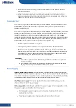
clearing. Besides, it is recommended that you should replace the anti-dust mesh 
every 3 or 6 months according to the clearness status of your equipment room. To 
purchase a new anti-dust mesh, contact Hillstone. 
SG-6000-E3968/E3960/E3960-GM/E3668/E3662/E3662-GM/SG-6000-
E3660/E2868/E2860/E2300/2800 has a built-in cooling system.  

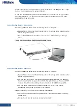
Figure 1-25: Air Circulation 


The ambient temperature of the working environment should keep between 0 and 
40 degree Celsius. If a small fan works abnormally, the system will alert you using 
the FAN LED. You must replace the fan tray with a new one. If two small fans work 
abnormally, the system will power off without saving the current configurations. 


Содержание SG-6000 E Series

Страница 1: ...Hillstone StoneOS User Manual Hillstone SG 6000 E Series Hardware Reference Guide www hillstonenet com TWNO TW HW ES EN V5 4 Y20M05...

Страница 2: ...hazardous substance in the material is below the limit requirement defined in Requirements for Concentration Limits for Certain Hazardous Substances in Electronic Information Products SJ T11363 2006...

Страница 3: ...r 4 Boot and Configuration Chapter 5 Hardware Maintenance and Replacement Chapter 6 Troubleshooting Appendix Supported Versions of Devices Addendum FCC Statement Document Conventions This guide uses t...

Страница 4: ...anel 9 LED Indicators 13 System Parameters 15 Ports 20 CLR Button 26 Expansion Slot 27 Power Supply 27 Hard Disk Modules 29 Expansion Modules 30 Cooling System 30 CHAPTER 2 INSTALLATION PREPARATIONS 3...

Страница 5: ...n 44 WebUI 45 Tenet and SSH 46 BASIC CONFIGURATION 46 CHAPTER 5 HARDWARE MAINTENANCE AND REPLACEMENT 47 INTRODUCTION 47 INSTALLING AND REMOVING THE POWER SUPPLY MODULE 47 INSTALLING AND REMOVING THE E...

Страница 6: ...Figure 1 19 SG 6000 E1100 WLAN version Back Panel 11 Figure 1 21 SG 6000 E1100 4G version Back Panel 12 Figure 1 23 AC Power Module 29 Figure 1 24 DC Power Module 29 Figure 3 1 Installing the Rubber...

Страница 7: ...scription of SG 6000 E1100 WLAN version 11 Table 1 17 Back Panel Description of SG 6000 E1100 4G version 12 Figure 1 22 SG 6000 E1100 WLAN 4G version Back Panel 13 Table 1 18 Back Panel Description of...

Страница 8: ...SG 6000 E5660 SG 6000 E5268 SG 6000 E5260 SG 6000 E5168 SG 6000 E3965 SG 6000 E3968 SG 6000 E3960 SG 6000 E3668 SG 6000 E3662 SG 6000 E3660 SG 6000 E2868 and SG 6000 E2860 adopt modular design of hot...

Страница 9: ...ent port 18 Fan tray The front panel of SG 6000 E6168 and SG 6000 E6160 consists of 2 Gigabit Ethernet ports 8 SFP ports 1 USB port 1 HA port 1 Management port 1 Console port 1 Auxiliary port 1 CLR bu...

Страница 10: ...orts 2 STA Status LED 9 CON Console port 16 e0 6 e0 9 SFP ports 3 ALM Alarm LED 10 AUX Auxiliary port 17 Slot 1 General expansion slot 4 HA HA status LED 11 Fan tray 18 Slot 2 General expansion slot n...

Страница 11: ...General expansion slot 5 PS0 Power supply PS0 LED 12 USB USB port 19 Slot 2 General expansion slot not for storage expansion module 6 PS1 Power supply PS1 LED 13 HA HA port 20 Slot 3 General expansio...

Страница 12: ...module SG 6000 E3668 SG 6000 E3662 SG 6000 E3660 SG 6000 E2868 and SG 6000 E2860 have the same front panel The front panel consists of 6 Gigabit Ethernet ports 4 SFP ports 1 USB port 1 Console port 1...

Страница 13: ...escription of SG 6000 E2800 and SG 6000 E2300 No Label No Label No Label 1 PWR Power LED 5 e0 0 e0 8 Gigabit Ethernet port status LED 9 USB USB port 2 STA Status LED 6 e0 5 e0 8 SFP interface LED 10 e...

Страница 14: ...8 Gigabit Ethernet port status LED 11 e0 0 e0 8 Gigabit Ethernet ports 4 HA HA status LED 8 CLR CLR button The front panel of SG 6000 E1600 consists of some LED indicators Figure 1 9 SG 6000 E1600 Fro...

Страница 15: ...rt status LED The front panel of SG 6000 E1100 4G version consists of some LED indicators Figure 1 12 Front Panel of SG 6000 E1100 4G version Table 1 12 Front Panel Description of SG 6000 E1100 4G ver...

Страница 16: ...6000 E6160 have the same back panel layout The back panel layout of SG 6000 E6368 SG 6000 E6360 SG 6000 E6168 and SG 6000 E6160 consists of 2 power supply sockets 2 expansion slots 1 grounding screw a...

Страница 17: ...6000 E3662 SG 6000 E3660 SG 6000 E2868 SG 6000 E2860 SG 6000 E2800 SG 6000 E2300 SG 6000 E1700 and SG 6000 E1606 have the same back panel layout The standard products SG 6000 E2800 SG 6000 E2300 SG 60...

Страница 18: ...el of SG 6000 E1100 WLAN version has 1 power supply socket 1 Console port 1 CLR button 9 Gigabyte Ethernet ports 1 USB port 1 grounding screw 1 security keyhole and 2 SMA connectors for WLAN antennas...

Страница 19: ...17 Back Panel Description of SG 6000 E1100 4G version No Label No Label No Label 1 SMA connector for 4G antenna 4 CON Console port 7 e0 0 e0 8 Gigabit Ethernet port 2 DC POWER DC power interface 5 SI...

Страница 20: ...hernet port LED Indicators The following table describes the meanings of LED indicators on the front panels of Hillstone devices Table 1 19 Front Panel LED Descriptions LED Color Status Description PW...

Страница 21: ...Off High Availability is disabled FAN Green Always on The cooling system is running normally Orange Always on One of the fans has failed but the cooling system can still fully function Change the fan...

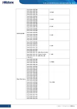
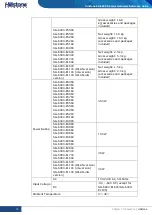
Страница 22: ...ent product models please refer to the actual product System Parameters The following table lists the system parameters of Hillstone devices of all models Table 1 20 System Parameters Item Description...

Страница 23: ...E3960 6 Gigabit Ethernet ports 4 SFP ports 2 SFP ports 1 USB 2 0 Host port 1 Console port 1 Auxiliary port 1 MGT port 1 HA port SG 6000 E3668 SG 6000 E3662 SG 6000 E3660 SG 6000 E2868 SG 6000 E2860 6...

Страница 24: ...6000 E2860 4 GB SG 6000 E3660 SG 6000 E2800 SG 6000 E2300 SG 6000 E1700 SG 6000 E1606 2 GB SG 6000 E1600 SG 6000 E1100 WLAN version SG 6000 E1100 4G version SG 6000 E1100 WLAN 4G version 1 GB Flash M...

Страница 25: ...60 SG 6000 E3668 SG 6000 E3662 SG 6000 E3660 SG 6000 E2868 SG 6000 E2860 436 0 mm x 365 5 mm x 44 0 mm SG 6000 E2800 SG 6000 E2300 SG 6000 E1700 SG 6000 E1606 442 0 mm x 240 7 mm x 44 0 mm SG 6000 E16...

Страница 26: ...rsion SG 6000 E1100 WLAN 4G version Net weight 1 5 kg Gross weight 2 0 kg accessories and packages included Power Rating SG 6000 E6368 SG 6000 E6360 SG 6000 E6168 SG 6000 E6160 SG 6000 E5960 SG 6000 E...

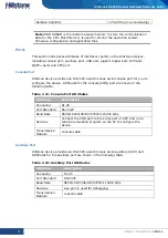
Страница 27: ...t for you to configure the device Attributes for the console CON port are shown in the following table Table 1 21 Console Port Attributes Attribute Description Connector RJ 45 Port Standard RS 232C Ba...

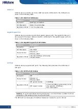
Страница 28: ...owing table Table 1 24 Gigabit Copper Port Attributes Attribute Description Connector RJ 45 Port Standard Auto MDIX Frame Format Ethernet_II Ethernet_SNAP Negotiation Mode 10 100 1000Mbps autosensing...

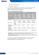
Страница 29: ...ule 1550nm Ultra long Haul Single mode Optical Module 1550nm Connector LC Fiber Type 62 5 125 m multi mode fiber 9 125 m single mode fiber 9 125 m single mode fiber 9 125 m single mode fiber 9 125 m s...

Страница 30: ...opper cable connection on Combo ports you need to first clear the rate and duplex mode configurations in the current operating mode copper or optical and re configure the port after the switching SFP...

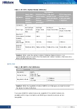
Страница 31: ...l Wavelength 850nm 1310nm 1550nm 1550nm Optional Factory Module TRAN SR SFP TRAN LR SFP TRAN SFP LX40 TRAN SFP LX80 Caution When using the optical module of Hillstone Network factory it is recommended...

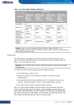
Страница 32: ...ength 850nm 1310nm Optional Factory Module TRAN SR QSFP TRAN LR QSFP Caution When using the optical module of Hillstone Network factory it is recommended not to mix with other manufacturers optical mo...

Страница 33: ...ise CLR Button The CLR button is the pinhole of the front panel and is used to reset the device back to the factory default settings You can restore access to the device with this button if the login...

Страница 34: ...pansion modules can only be installed in Slot2 and Slot4 More than one expansion modules of the same type can be inserted in the device Only one IOC 4SFP or IOC 8SFP interface expansion module can be...

Страница 35: ...e SG 6000 E5168 SG 6000 E3965 Dual AC DC Hot swappable SG 6000 E3968 SG 6000 E3960 Single Dual AC DC Fixed SG 6000 E3668 SG 6000 E3662 Single Dual AC DC Fixed SG 6000 E3660 Single Dual AC DC Fixed SG...

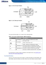
Страница 36: ...Always on Power module has error Off Power module is functioning normally AC Green Always on AC power module is functioning normally Off AC power module is powered off or has failed DC Green Always o...

Страница 37: ...atforms specifically including interface module and storage module The main functions of these expansion modules are Interface module Expands the number of ports Storage module Enlarges the hardware s...

Страница 38: ...ntact Hillstone SG 6000 E3968 E3960 E3960 GM E3668 E3662 E3662 GM SG 6000 E3660 E2868 E2860 E2300 2800 has a built in cooling system Figure 1 25 Air Circulation The ambient temperature of the working...

Страница 39: ...vention To prevent electrostatic discharge ESD damage ensure that The device is well grounded The grounding screw is properly grounded Take dustproof measures for the equipment room Maintain proper hu...

Страница 40: ...ck is well grounded Other Safety Recommendations The directions below are also recommended for you to follow Keep the device far away from moist areas and heat sources Wear an ESD wrist strap correctl...

Страница 41: ...Preparations Hillstone Hillstone SG 6000 E Series Hardware Reference Guide Terminal Configuration terminal e g an ordinary PC Tools Philips screwdrivers and ESD wrist strap Cables Power cable console...

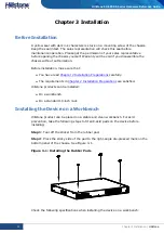
Страница 42: ...e that You have read Chapter 2 Installation Preparations carefully The requirements in Chapter 2 Installation Preparations are satisfied Hillstone products can be installed On a workbench On a standar...

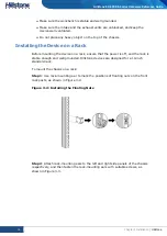
Страница 43: ...ounting the device on a rack ensure that the power is off and the rack is stable enough and well grounded Hillstone devices are designed for a 19 inch standard rack To mount the chassis on a rack Step...

Страница 44: ...Figure 3 4 Installing the Device in a Rack 1U Chassis as example Cautions The rack mounting ears cannot bear weight Make sure the chassis is supported by the platform under it when mounted into a rac...

Страница 45: ...ich has an RJ 45 connector that can be connected to the Console port of the device and a DB 9 female connector that can be connected to the serial port of a console terminal Perform the following step...

Страница 46: ...ction use crossover cable or straight through cable Figure 3 6 Connecting the Ethernet Copper Cable Connecting the Ethernet Fiber Cable Follow the guidelines below when connecting cables to the ports...

Страница 47: ...contact in advance Normally the ground contact of the power supply system in a building was buried during construction and cabling Before connecting the AC input power cable you must make sure that th...

Страница 48: ...Ensure that the power source voltage is in accordance with required voltage specified in System Parameters 2 Switch off the power source 3 If the terminal on the power supply module has a plastic cove...

Страница 49: ...power adapter into the AC power interface at the back panel of the device 2 Connect the power adapter to the external AC power supply Installing an Antenna To use the WLAN 4G function of the device y...

Страница 50: ...the back panel of the device Note 4G data card and SIM card must match the network type Verifying Installation After you complete the installation with all the above steps you still need to verify the...

Страница 51: ...connection WebUI Telnet or SSH Console CON Connection For initial system configuration you have to establish a Console connection environment connect the device to a configuration terminal through it...

Страница 52: ...and password prompts press Enter And now you are successfully logged in and accessing the CLI 4 Enter commands to configure or view running status Enter a question mark to get help on commands wheneve...

Страница 53: ...and your network deployment Different device position in the network requires different topology design working mode and policy configuration The basic configurations may include 1 Create security zon...

Страница 54: ...llowing steps to install or remove the power supply module To install a power supply module take the following steps 1 Ensure that the power supply module to be used is not connected to any power sour...

Страница 55: ...feel resistant 5 Tighten the screws on the expansion module To remove an expansion module 1 Make sure the power is switched off and you should wear the ESD strap properly 2 Face the front panel of the...

Страница 56: ...0 E5560 SG 6000 E5268 SG 6000 E5260 SG 6000 E5168 and SG 6000 E3965 are designed with anti dust mesh This section describes the installation and remove of anti dust mesh The anti dust mesh is hot swap...

Страница 57: ...ollowing steps to install the hard disk module 1 Make sure the device is not powered and you have worn antistatic gloves 2 The hard disk module is at the bottom of the device so you should turn over t...

Страница 58: ...SG 6000 E Series Hardware Reference Guide Figure 5 4 Placing the Hard Disk Module 5 Use the screw in the hard disk module package to fix the hard disk module Figure 5 5 Fixing the Hard Disk Module 6 U...

Страница 59: ...you should turn over the device to make sure the hard disk module is visible In order to avoid the top of the device being scratched make sure the workbench is stable and clean 3 Use a screwdriver to...

Страница 60: ...ollowing steps Make sure the power supply cable is connected correctly Ensure that the voltage of the power source conforms to the required voltage For the PWR LED information see LED Indicators Troub...

Страница 61: ...lows You can also call 1 800 889 9860 for more help about updating Note The devices which are not listed in the following table can update normally The devices in the Table 1 which are produced before...

Страница 62: ...000 SG 6000 NAV20L SG 6000 NAV55 SG 6000 P935 SG 6000 P936 SG 6000 P912 SG 6000 P912_I SG 6000 P915 SG 6000 P916 SG 6000 P926 SG 6000 P932 SG 6000 P932_I SG 6000 P1246E SG 6000 P1246E I SG 6000 P1256...

Страница 63: ...Now The 7th week of 2017 Now Yes 5 5R2P14 and later P versions 5 5R4P9 and later P versions 5 5R5P7 and later P versions 5 5R6P2 and later P versions 5 5R7 and later versions No 5 0R4P18 and later P v...

Страница 64: ...ices to the supported versions if SN is within the range Whether IOC 2SFP lite is Used Device Supported Versions 5 5R6P2 and later P versions 5 5R7 and later versions No 5 0R4P14 and later P versions...

Страница 65: ...te This equipment has been tested and found to comply with the limits for a Class B digital device pursuant to part 15 of the FCC Rules These limits are designed to provide reasonable protection again...

Страница 66: ...that may cause undesired operation of the device This class B digital apparatus complies with Canadian ICES 003 IC Radiation Exposure Statement This equipment complies with IC radiation exposure limi...

Страница 67: ...ed the test which was performed according to the following European standards ETSI EN 300 328 V1 8 1 2012 06 EN 301 893 V1 7 1 2012 06 EN 62311 2008 EN 301 908 1 V5 2 1 EN 301 908 2 V5 2 1 EN 301 511...

Страница 68: ...lstone PnPVPN UTM Plus are trademarks of Hillstone Networks All other trademarks or registered marks are the property of their respective owners Hillstone Networks assumes no responsibility for any in...

Отзывы: