background image

Fixed-angle  Speed-measuring  Radar


  14 

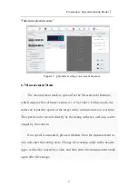
6.5 Speed Measurement State 

After the successful connection,it is assumed to be the state of speed 

measurement. When a vehicle passes the certain position, the speed displ- 

ay area will display the current speed and record the data,as shown in Fi- 

gure 15. 


Figure15    speed measurement state 

6.6 Parameter Setting 

Click the "state set" in "function selection zone", and the parameters 

setting is activated while speed detection function is closed. 

Содержание DS-TD10N-1

Страница 1: ...Fixed angle Speed measuring Radar FIXED ANGLE SPEED MEASURING RADAR PRODUCT MANUAL V12 0 0 2020 1...

Страница 2: ...se read the product manual carefully All copyrights reserved by HIKVISION shall not be violated Other wise HIKVISION possesses the right to require legal responsibilities fro m the violator The Manual...

Страница 3: ...nstallation 7 4 3 Communication Connection 8 5 Communication Protocol 9 5 1 Protocol Description 9 5 2 Protocol Message 9 6 Software Usage 9 6 1 Software Installation 10 6 2 Software Interface 10 6 3...

Страница 4: ...Fixed angle Speed measuring Radar 2 8 Maintenance and Common Fault diagnosis 20 8 1 Use Cautions 20 8 2 Common Fault diagnosis 20...

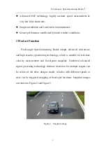
Страница 5: ...module enables an easy integration as there are no settings required It can be widely applied to gantry tunnel three dimensional crossing bridges and other traffic environments Figure1 Fixed angle Spe...

Страница 6: ...Speed measuring Radar adopts advanced microwave and high accuracy positioning technology which is suitable for real time velocity measurement and fixed point snapshot Combined advanced signal processi...

Страница 7: ...adar the connector is canceled which effectively prevent the negative i mpact caused by connecting disconnecting the wire harness frequently Meanwhile a WiFi function is added to this radar parameters...

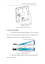
Страница 8: ...or 100km h 0 5 0 km h 100km h 1 0 km h Voltage Range 9 V 12V DC Current Range 0 3A Power Dissip 2W Temp Range 40 80 4 Installation Instruction 4 1 Bracket Installation Bracket can connect fix adjust a...

Страница 9: ...e radar is usually mounted on the gantry L bar etc fixed on the top of the driveway Radar detection direction is aligned with the snapshot position which is in the middle of the driveway Figure 6 inst...

Страница 10: ...rease the installation efficiency The radar is also applicable to multiple lanes Figure 7 Fixed angle Speed measuring Radar used in multiple lanes installation diagram 4 3 Communication Connection Nam...

Страница 11: ...otocol 5 1 Protocol Description The radar data communication adopts RS485 or RS232 baud rate 9600bps data bits 8 bits stop bits 1 no checkout bits 5 2 Protocol Message The radar sends the speed packet...

Страница 12: ...ion After installation the Fixed angle Speed measuring Radar debugging software shortcut will be generated on the desktop as shown in Figure 9 Figure 9 Fixed angle Speed measuring Radar shortcut 6 2 S...

Страница 13: ...sensitivity speed limit speed correction etc Speed display zone displays the current measurement speed speed recording and animation display Parameter settings zone carries parameter settings paramete...

Страница 14: ...ram If the Serial mode is selected The software can automatically identi fy all available ports and users can choose the corresponding ports ac cording to the radar the specific port number can be see...

Страница 15: ...State Display After the successful connection the state display zone will show the current state of the radar including software version product se quence number serial number of the main board radar...

Страница 16: ...measurement When a vehicle passes the certain position the speed displ ay area will display the current speed and record the data as shown in Fi gure 15 Figure15 speed measurement state 6 6 Parameter...

Страница 17: ...mode and continuous triggering mode 1 Front triggering mode measure moving vehicles straight coming data delivery one time of each vehicle no data delivery without vehi cles 2 Rear triggering mode me...

Страница 18: ...recommended Upper limit lower limit the highest and minimum speed values of measurement required Speed accuracy correction it is necessary to correct the speed detect ed by radar on some occasions The...

Страница 19: ...is 1 0 0 or above In this mode the radar can report the speed of the target in the measured area in real time The speed can be viewed directly by the debug software and also can be caught by the camer...

Страница 20: ...ry to disconnect the device or restart the software Chick program upgrade in func tion selection zone and set the corresponding serial port pa rameters in the pop up connection setting baud rate 9600...

Страница 21: ...in the software version of 1 0 0 and above The previous versions are upgraded by cold boot 7 Radar Status Indicator light There are two indicator light in Fixed angle Speed measuring Radar red one is...

Страница 22: ...Common Fault diagnosis Debugging software cannot be connected 1 Verify the power connections to the radar check that the green light is on 2 Check the serial port is connected firm or not and whether...

Страница 23: ...test again 4 Check there is strong electromagnetic interference nearby or not Speed can be detected without car 1 Check the radar is aimed at the target lane or not 2 Check there is strong electromag...

Страница 24: ...Fixed angle Speed measuring Radar 22...

Отзывы: