Video Wall Controller • User Manual
6
Enter Video Wall Configuration
→
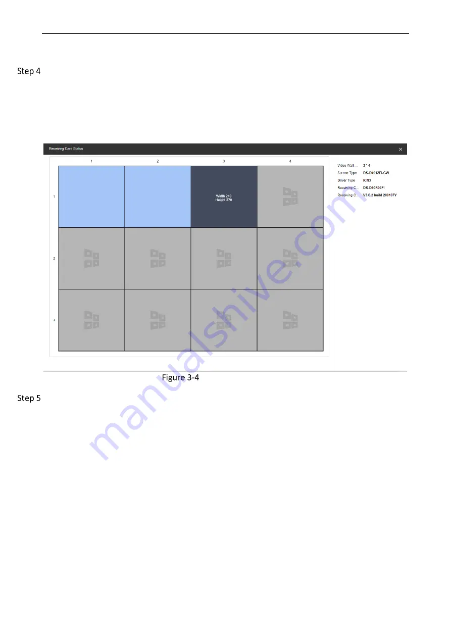
Decoding Output. Select LED sending card in the Output List
(Example of naming the LED sending card: LEDSendCard_Board19_1). Right-click and select
Receiving Card Status.
The following figure shows an example: The receiving card has 2 sending ports. Blue means that
the receiving card is in normal state. On the right, users can view the video wall size, screen type,
receiving card type, version and other information.
View the Receiving Card Status
Enter Video Wall Configuration
→
Decoding Output. Select LED sending card in the Output List
(Example of naming the LED sending card: LEDSendCard_Board19_1). Right-click and select Signal
Cable Configuration.
1. Click Load from the Screen, the screen type will be displayed automatically.
2. Click Signal Source Configuration. Check Display Actual Lines on Screen.
3. Click the sending port of the sending card on the left.
4. According to the cabinet number on site, click the frame on the right to connect the sending
card with the cabinet screen.
5. The following parameters can also be set during the connection.
Marking Type: Supports quick connection according to the layout of the receiving card on site.


