background image

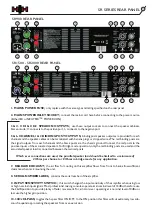
SR SERIES REAR PANEL

SR900 REAR PANEL

SR1500 - SR2000 REAR PANEL

1.  MAINS POWER FUSE;

  only replace with the same type and rating specified on the rear panel.

2.  MAINS POWER INLET SOCKET; 

 connect the mains cord here before connecting to the power source. 

(Either IEC or NEUTRIK 

POWERCON)

3 & 4.   CH1 & CH2   SPEAKON OUTPUTS; 

 use these output sockets to connect the speaker cabinets. 

Stereo mode: 1+ connects to the positive port, 1- connects to the negative port. 

5 & 6.  CHANNEL 1 & 2  BINDING POST OUTPUTS; 

 binding post speaker outputs are provided for each 

channel and the speaker cables can be terminated with banana plugs or stripped wires. The red binding posts are 
the signal outputs from each channel and the black posts are the chassis ground. Connect the red posts to the 
positive inputs of the associated speakers. For Bridge mode operation, only the red binding posts are used and the 
associated speaker load is connected between the two red posts.

Which ever connections are used, the parallel speaker load should be limited to a minimum of

4 Ohms per channel or 8 Ohms in bridge mode for any application.

7.  REAR AIR EXHAUST; 

 the air flow for cooling on this amplifier flows from front to back, allow sufficient 

clearance when rack mounting the unit.

8.  SERIAL NUMBER LABEL;

  contains the serial number of the amplifier.

9.  INPUT SENSITIVITY SWITCH;

  this switch changes the input sensitivity of the amplifier when using low 

or high nominal input signals. Most professional mixing consoles operate at a nominal level of +4dBu; therefore use 
the 26dB position to provide plenty of fader movement. For a disco mixer operating at a nominal level of 0dBu or 
less use the higher gain position.

10. 30Hz HI-PASS; 

 toggles the hi-pass filter ON/OFF.  In the ON position this filter will cut extremely low sub-

sonic frequencies, protecting the speakers from over-excursion

™ 

Содержание SCALAR SR Series

Страница 1: ...PROFESSIONAL POWER AMPLIFIER WWW HHELECTRONICS COM...

Страница 2: ...rucciones Importantes Para Su Seguridad Espa ol Important Safety Instructions Pt 2 Foreword Introduction SR Series Front Panel SR Series Rear Panel SR Series Setup Connections Block Diagram Specificat...

Страница 3: ...apparatus the apparatus has been exposed to rain or moisture does not operate normally or has been dropped 15 Never break off the ground pin Connect only to a power supply of the type marked on the un...

Страница 4: ...nne l assaut ou si inutilis pendant de longues p riodes 14 Seul un technicien agr par le fabriquant est m me de r parer contr ler votre unit Celle ci doit tre contr l e si elle a subit des dommages de...

Страница 5: ...technikern durchf hren Eine Wartung ist erforderlich wenn das Ger t in irgendeiner Art besch digt wurde etwa wenn das Netzkabel oder der Netzstecker besch digt wurden Fl ssigkeit oder Gegenst nde in d...

Страница 6: ...g n objeto ha ca do dentro del aparato el aparato ha sido expuesto a la lluvia o la humedad no funciona de manera normal o ha sufrido una ca da 15 Nunca retire la patilla de Tierra Conecte el aparato...

Страница 7: ...user of the presence of important operating and maintenance Servicing instructions in the literature accompanying the product Dieses Symbol soll den Anwender vor unsolierten gefahrlichen Spannungen i...

Страница 8: ...s much as we enjoyed creating it By choosing HH you are joining a brand with heritage dating back to 1968 a brand that helped define the techniques and principles for sound reinforcement and backline...

Страница 9: ...using the equipment in a rack consideration should also be given to cooling The air flow through the unit from front to back should not be obstructed or hindered in any way so adequate ventilation in...

Страница 10: ...D When the surround is RED the amplifier has reached its maximum power output The distortion is around 0 5 5 PARALLEL INDICATOR shows when the amplifier is in Parallel mode i e acting as two separate...

Страница 11: ...ration only the red binding posts are used and the associated speaker load is connected between the two red posts Which ever connections are used the parallel speaker load should be limited to a minim...

Страница 12: ...either XLR or Jack 14 CHANNEL 1 LINK this socket is in parallel with CH1 Combi Skt and provides an output signal same as the input signal 15 CHANNEL 2 LINK this socket is in parallel with CH2 Combi S...

Страница 13: ...connected to each channel set the mode switch to Stereo connect a speaker cabinet to each channel output and adjust the two gain controls usually set to full power and then control the output from the...

Страница 14: ...put CH2 Combi Input CH1 Link XLR M CH2 Link XLR M Attenuator Attenuator Bridge Parallel Stereo Mode Switch Protection Circuit 26dB 32dB Sens Switch Channel 1 Preamp Channel 2 Preamp HI Pass Switch Out...

Страница 15: ...20V s 20V s 20V s Damping Factor 8 Ohm Stereo 1 KHz sine 30 10 200 250 200 Dynamic Range 8 Ohm Stereo 5dB 80dB 80dB 80dB S N Ratio 20Hz 20KHz 5dB 90dB 85dB 85dB Crosstalk 8 Ohm Stereo 1 KHz sine 5dB 7...

Страница 16: ...t to the speakers will be cut The output signal will return within 10 seconds after the removal of the short circuit 5 AC Local Power Protection if theAC power voltage drops too low 160V in the case o...

Страница 17: ...1 2 3 Gnd Gnd Gnd 2 2 1 1 Balanced XLR 6 3mm Balanced Jack 6 3mm Unbalanced Jack Speakon TIP RING SLEEVE TIP SLEEVE HOT COLD GROUND HOT GROUND 1 POSITIVE 1 NEGATIVE 2 NOT USED 2 NOT USED 1 GROUND 2 PO...

Страница 18: ...NOTES...

Страница 19: ...NOTES...

Страница 20: ......

Отзывы: