# 372449 | Version 3.2
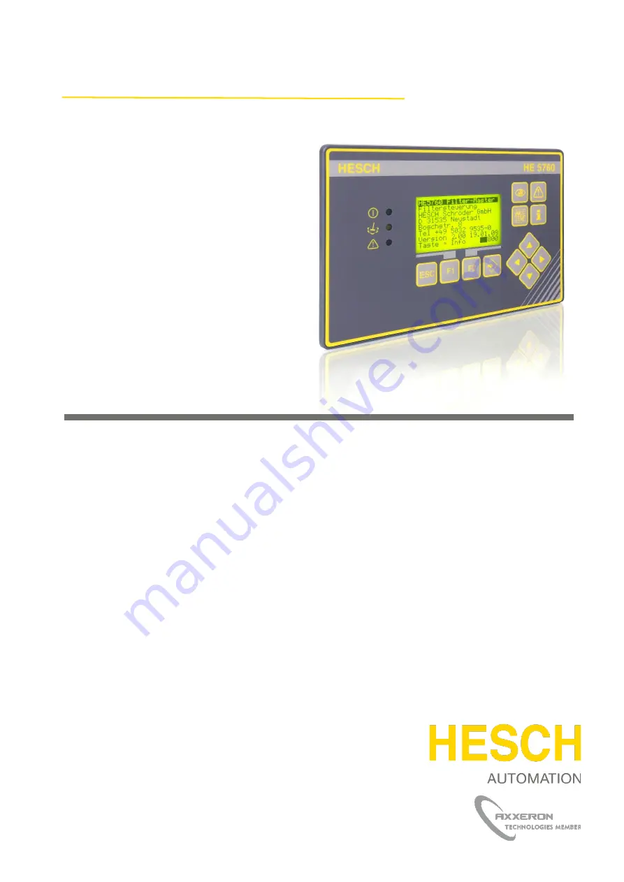
Filter Control
HE 5760
Operating instructions
(Translation of Original German version)
Страница 1: ...372449 Version 3 2 Filter Control HE 5760 Operating instructions Translation of Original German version...
Страница 2: ...ished by HESCH Industrie Elektronik GmbH Documentation Department Copyrights Copyright 2021 HESCH Industrie Elektronik GmbH All rights reserved The content including pictures and the design of these o...
Страница 3: ...on no added Layout change title page imprint added Section 3 5 amended Description changed Section 1 3 amended HE 1149 Image updated Chapter 1 3 4 HE 5410 Picture updated 18 01 2019 3 1 System expansi...
Страница 4: ...ation through control signals 18 7 2 ELECTRICAL CONNECTION HE 5725 19 7 3 CAN NETWORK CONFIGURATION 20 7 3 1 CAN address assignment 20 7 3 2 CAN address setting on HE 5725 21 7 3 3 CAN termination 21...
Страница 5: ...Valve error 46 10 2 5 Valve control tank pressure sensor error 46 10 2 6 Valve control Tank pressure error sensor is OK 46 11 COMMUNICATION 47 11 1 MASTER HE 5760 SLAVE HE 5725 COMMUNICATION 47 11 2...
Страница 6: ...designed for installation in control cabinets Local operation at the control cabinet with switchgear and signal lamps that are connected directly is possible The device can be operated within the oper...
Страница 7: ...rity of the danger is indicated by the respective signal word Explosive region warning sign High Voltage Warning Warning of material damage caused by electrostatic charge Property Damage Warning Note...
Страница 8: ...tional interruptions are not permitted If there is a suspicion that it is no longer possible to operate the device safely it must be shut off and secured against being unintentionally switched on Dang...
Страница 9: ...faults on additional devices or supply lines measuring lines wiring downstream devices should be taken into consideration If the fault is not found after checking these points we recommend sending the...
Страница 10: ...e Modbus RTU Profibus Inputs 5 Digital inputs 24 V DC galvanically isolated for local operation Operation on the control cabinet with keys and indicator lights 2 analogue inputs 4 20 mA for system pre...
Страница 11: ...cified in the technical data 4 1 Dimensions The HE 5760 is a panel mounted unit with the following dimensions Figure 1 HE 5760 Dimensions Scope of Delivery HE 5760 Premium Operating instructions Note...
Страница 12: ...5725 CAN Figure 2 System overview HE 5760 HE 5725 5 1 System components 5 1 1 Master control HE 5760 Central control of the filter system To be connected CAN line Pressure sensor for system pressure a...
Страница 13: ...CAN slave 12 valves are connected directly as well as the pressure sensors of the local pressure tanks Figure 4 HE 5725 5 1 3 HE 1149 Used to measure the compressed air at the central supply system pr...
Страница 14: ...of the contamination of the filter system Measuring range 0 100 mbar Figure 6 HE 5410 5 2 Filter system P P Figure 7 Filter sketch 1 Raw gas 2 Clean gas 3 Differential pressure measurement raw gas cle...
Страница 15: ...view current alarms and the alarm list Command and control keys Exit the current menu without changing the value Context menu keys meaning is shown in the lowest text line of the display Selection of...
Страница 16: ...ring operation The protective conductor connection in the corresponding equipment rack must be conductively connected to the protective conductor Danger of Electrocution Electrical installation must o...
Страница 17: ...Termination Bus termination switchable Digital Out 24 V DC status signals 7 Operation green LED 8 Cleaning yellow LED 9 Malfunction red LED 10 Pulse 11 Out GND Analogue In 4 20 mA Pressure measurement...
Страница 18: ...ructions 372449 Version 3 2 7 1 1 Local operation through control signals 1 2 3 4 5 6 Figure 10 Example of the possible use of the control signals 1 Operation 2 Cleaning 3 Malfunction 4 Local Remote 5...
Страница 19: ...35 Valve 4 PE 8 Valve 5 22 Valve 5 GND 36 Valve 5 PE 9 Valve 6 23 Valve 6 GND 37 Valve 6 PE Pressure 1 16 24 V DC Out 30 Sensor 1 GND 44 PE IN Out CAN Connection 46 50 CAN H 47 51 CAN L 48 52 CAN GND...
Страница 20: ...in rules The HE 5760 control unit does not require a CAN address With the HE 5725 valve controls a distinction is made between one HE 5725 per chamber consecutive numbering 1 2 3 48 two HE 5725 per ch...
Страница 21: ...Figure 14 Address setting on HE 5725 7 3 3 CAN termination A CAN network must be terminated at both ends The termination is switchable at the units If the termination is faulty the technical bus commu...
Страница 22: ...of the CAN bus communication is fixed at 50 kBaud The maximum bus extension can be up to 1200 m 7 3 4 Termination on HE 5760 and HE 5725 For termination the jumper is plugged into the positions shown...
Страница 23: ...cessary variables pressures etc Existing alarm messages are signalled by the red LED The messages can be called up with the alarm key Chapter 10 Error messages provides additional information on troub...
Страница 24: ...lowing screen Standard screen for an overview of the most important values Current chamber Current valve Differential pressure value and symbol System Pressure Differential pressure symbol Depending o...
Страница 25: ...24 hours using the UP and DOWN keys Time scaling selectable via Graphical representation of the dust The display period can be selected from 20 seconds to 15 minutes using the UP and DOWN keys The ac...
Страница 26: ...00 17 03 14 Time Service Clock setting 08 01 14 Tue 08 46 16 Set Important information The fields can be freely described Operator manufacturer service or emergency call information Further informatio...
Страница 27: ...tal inputs Input 1 OFF Input 2 OFF Input 3 OFF Input 4 OFF Input 5 OFF ESC Back Password input Level HE5760 Input 8 5 Communication structure The HE 5760 central control unit is the master in the syst...
Страница 28: ...nd down keys to enter the required values or select settings The Enter key accepts the change the ESC key allows you to cancel the entry at any time without making a permanent change After parameteris...
Страница 29: ...10 0 60000 0 ms Technician 4 7 1 Control time pause 50 0 1 0 3600 0 s Technician 4 8 2 Control time pulse 0 0 0 0 60000 0 ms Technician 4 9 2 Control time pause 0 0 0 0 3600 0 s Technician 4 10 Press...
Страница 30: ...Delta p 30 0 9 9 799 0 mbar Technician 11 3 Pressure 6 0 1 0 799 0 bar Technician 11 4 System pressure function 1 0 1 yes no Technician 11 5 Delta p filter 0 0 0 0 999 0 s Technician 11 6 Dust 49 9 4...
Страница 31: ...is measured during valve actuation The pressure drop during valve actuation and the pressure rise afterwards must reach certain values in order not to report a valve fault The values can be set with...
Страница 32: ...elf works language independently with internal text numbers Each text number stands for a word or phrase This parameter selects the current language set The complete text list for the 2 Language must...
Страница 33: ...meters 11 4 11 14 4 2 Cleaning mode PartCycle 0 TotalCyc 1 Setting whether to clean with complete cycles or with partial cycles 4 3 Manual cleaning mode Permanent Threshold Regulation Defines the star...
Страница 34: ...binations can be selected Function After a valve has been activated the pressure in the local pressure tank must fall below a certain value If not an error message is generated After closing the valve...
Страница 35: ...ve that is to be operated simultaneously has its own parameter Precondition Valves to be controlled simultaneously are not connected to the same valve control unit The parameter is understood as an of...
Страница 36: ...f the dp value is still smaller it is assumed that the system is switched off and background cleaning is not performed 9 3 6 Chamber control 6 1 Chamber shut off Yes No A chamber can be removed from t...
Страница 37: ...000 cycles Interval for the service related to the cleaning cycles 9 3 9 Autostart Timeout 9 1 Autostart delay 0 0 14400 9 2 Remote timeout 0 0 14400 9 3 Local timeout 0 0 14400 9 3 10 Passwords Anyon...
Страница 38: ...t evaluate the system pressure can be switched off 11 5 Delta p filter 0 0 1 0 999 0 s The process signal is provided with a 1st order low pass filter This value is displayed and processed internally...
Страница 39: ...or active alarms Yes Low for active alarms 9 3 13 Dust monitoring 13 1 Central dust sensor No A In 1 A In 2 Selection of which analogue input the central dust sensor was connected to No 1 2 No deactiv...
Страница 40: ...ey is only visible there if valves are currently locked The dust contaminated valves are displayed in the alarms list until the function key Reset Dust Valves is pressed Yes option 2 Like Yes Opt 1 In...
Страница 41: ...eds the upper threshold 14 3 Delta p offset 0 0 799 0 799 0 mbar A value that is added to the cleaning thresholds This increases the filter effect The interpolation points of the filter curve are also...
Страница 42: ...pause time reduction is derived from the filter characteristic entered The pause time is calculated by a PID control algorithm Very large pause times are calculated especially with low differential p...
Страница 43: ...versely Display Criterion Cause Remedy Bus error inverse node no Communication with node failed CAN line interrupted or not connected HE 5725 Voltage missing HE 5723 defective Fuses tripped CAN line n...
Страница 44: ...alarm key Alarm protocol 2 17 03 14 10 17 18 Ch 1 Manifold press 1 low 1 Bus Error 3 17 03 13 10 17 19 Ch 2 Valve control 1 Bus Error Acknowl 200 10 2 1 Sensor error Display Criterion Cause Remedy Ana...
Страница 45: ...Alarm too low No throttle cable Delta p sensor error Value corresponds to the highest or lowest limit Open line to the sensor Short circuit on the sensor System pressure High Alarm System pressure ex...
Страница 46: ...ue for pressure rise too high Ch 3 Valve 5 no pressure Tank pressure has not recovered within the tank refill time Valve defective Tank refill time too low System pressure too low 10 2 5 Valve control...
Страница 47: ...e drop No pressure rise No pressure before activation Unsigned char 4 1 Digital 5 Valve error Unsigned char 5 1 Digital 6 0 1 2 3 Sensor error status Pressure 1 Sensor break Pressure 1 Sensor lock Pre...
Страница 48: ...d unsigned char 1 Remote control 2 Cancel Close chamber on site 3 Delta p offset activated 4 Time synchronised 5 Dust monitoring blocked 2 Close chamber Digital 1 0 Chamber 1 unsigned char to 7 Chambe...
Страница 49: ...chamber Digital 1 0 Chamber 33 unsigned char to 7 Chamber 40 13 Clean chamber Digital 1 0 Chamber 41 unsigned char to 7 Chamber 48 14 Delta p offset lower threshold signed short 2 16 Delta p offset u...
Страница 50: ...Digital 1 0 Test function activated unsigned char 1 Delta p offset activated 2 Time synchronised 3 reserved 4 Dust monitoring blocked 2 Current chamber Unsigned char 1 3 Current valve Unsigned char 1...
Страница 51: ...0 15 Chamber cleaning in progress Digital 1 0 Chamber 41 to Unsigned char 7 Chamber 48 16 Alarms 1st part Digital 1 0 Collective alarm Unsigned char 1 Differential pressure alarm 2 Error compressed ai...
Страница 52: ...ve error Digital 1 0 Line break Unsigned char 1 Overcurrent 2 No blowing pressure 3 Valve does not open 4 Valve does not close 5 Dust pre alarm 6 Dust main alarm 26 Number of the faulty valve Unsigned...
Страница 53: ...Second header 1 Slave status Digital 1 0 Slave 1 not connected Unsigned char 1 Slave 1 Error 2 Slave 2 not connected 3 Slave 2 Error Second header 2 Pressure alarms Digital 1 0 Pressure tank sensor 1...
Страница 54: ...pecific diagnosis 5 0 Length 33 byte Fourth header 1 Chamber 33 Data structure like chamber 1 Digital 2 To Fourth header 31 Chamber 48 Data structure like chamber 1 Digital 2 Additional information Of...
Страница 55: ...9 2 Parameter table The dust curve is shown over different time windows The Y axis of the monitoring graph is dynamically scaled Figure 19 Trend chart dust course The Y axis of the monitoring chart is...
Страница 56: ...ding is stopped in the display but continues in the background Note The graph is generated from volatile data which is stored in memory at runtime Power failure leads to loss of history 12 1 Reset of...
Страница 57: ...tch metals and plastics for recycling Electrical and electronic components must be collected separately and disposed of properly Dispose of equipped circuit boards properly Service HESCH Industrie Ele...
Страница 58: ...not continued Chamber sequence A chamber offset of 1 causes chamber 1 valve 1 chamber 2 valve 1 chamber 3 valve 1 etc to be cleaned A chamber offset has a higher priority than a valve offset A chambe...