

6
Operating conditions (Combustion control)
18
Betriebsanleitung_firematic_20-301_Touch_Englisch V1.2
present in the combustion chamber will not be
burnt correctly.
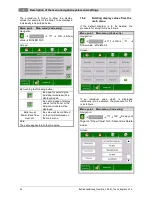
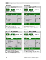
6.10
Burner cleaning
During burner cleaning the burner is cleaned of
ash. Firstly the fuel is burnt out. When the burnout
time is completed, then the burner plate is
cleaned. After successful cleaning the equipment
goes back into normal mode. The interval is
calculated via the runtime of the plug-in screw.
This can be set via the CLEANINTERVAL
parameter, i.e. in order to achieve more frequent
cleaning
of
the
combustion
chamber
the
parameter simply has to be shortened.
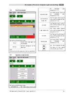
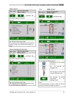
6.11
Heat exchanger cleaning
Heat exchanger cleaning serves to increase the
degree of efficiency. Here the heat exchanger is
automatically cleaned and the fly ash falls into the
so-called fly ash chamber.
The interval and duration of the cleaning can be
set via the HEC INTERVAL or HEC DURATION.
6.12
Output control
The output control is controlled within the boiler
target temperature and the control end phase.
The control end phase is the boiler target
temperature + control hysteresis. When the
control end phase is reached the equipment goes
to burnout.
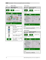
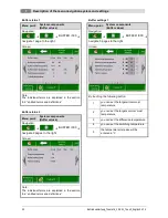
6.13
Flue gas temperature control
When the maximum flue gas temperature is
exceeded, then the output of the equipment is
reduced. If the temperature is not reached the
equipment goes back to normal output control.
6.14
Flame monitoring
Where the combustion values fluctuate too greatly
during operation, this is detected and the
equipment is switched off.
6.15
Frost protection
When the equipment goes into frost protection
then the return flow bypass pump is switched on
provided that the equipment is in “HEATING OFF”
or “BURNER STOP” condition. Otherwise the
equipment is started up and started up to a
minimum temperature of 65°C.
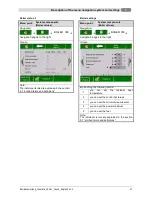
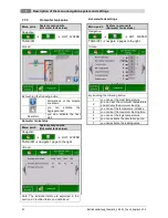
6.16
Lambda control
The amount of material and the suction ventilator
are controlled via the lambda control. This serves
to optimise the combustion and can detect slight
fuel fluctuations. Therefore, it is not necessary to
re-set the combustion after the silo is filled.
6.17
Room discharge
A room discharge screw can be connected to the
control.
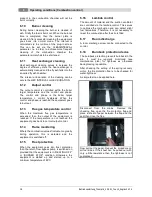
6.18
Burnback protection device
The burnback protection prevents burnback in the
silo. It must be regularly monitored (see
maintenance plan) for tightness as otherwise
back-glossing is possible.
After checking the setting of the spring recovery
motor, the fire protection flap is to be checked for
water-tightness.
A simple test can be applied here.
Disconnect from the mains. Remove the
checking flap, open the fire protection flap and
place a sheet of paper between the flap and the
seal then close the flap.
Now pull out the paper. Repeat the procedure on
all four sides. If the sheet can be pulled out with
only a little resistance then the tightness is not
guaranteed.