22
for the technician
First firing, regulation and servicing instructions
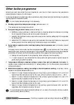
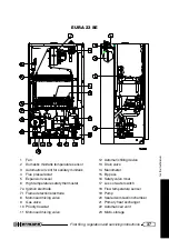
— To make gas pressure controls, insert manometer probes in pressure tapping points available
on to gas valve (see picture).
Note: To check that gas pressure and flowrate are sufficient to guarantee perfect boiler operations,
make such controls while burner is working.
MAX-MIN pressure adjustment
on GAS valve
— Unscrew (2-3 rounds) the screw in outlet pressure tap-
ping point [1] on gas valve and plug in manometer
probe. On “SE” models, unplug silicon rubber pipe (com-
ing from sealed chamber) from “Vent” plug [3];
— start the boiler at maximum power (not modulating)
proceeding
preferably
as described in “Combustion
check” paragraph; as alternative, proceed as follows:
•
set the domestic hot water temperature to the
maximum value;
•
open an hot water tap fully (flow rate 10 l/minute,
open more than one tap if needed), wait for the
stabilization of the pressure (at least 20 seconds);
— verify that pressure correspond to the MAX value indi-
cated in the table “BURNER POWER / PRESSURES”
(see following pages);
— unplug one of modulation coil supply connectors [4]
and check that pressure correspond to the MIN value
indicated in the table “BURNER POWER / PRES-
SURES”, then plug the connector back in;
— if it is necessary to adjust settings, proceed as follows,
according to the figure:
•
remove protection cap [C];
•
adjust MAX pressure by turning bigger nut [B] (8 mm). Clockwise to increase pressure,
counterclockwise to decrease;
•
unplug again one of connectors [4];
•
adjust MIN pressure by turning smaller nut [A] (5 mm) while keeping bigger nut [B] stopped.
Clockwise to increase pressure, counterclockwise to decrease;
•
insert connector [4] again and check that MAX pressure is not changed;
•
Fit cap [C];
Important: lock the adjustment device after any setting operation.
GAS VALVE
Pressure tapping pionts:
1 = Gas OUT
2 = Gas IN
3 = “Vent” plug (SE models)
872_R00
1
B
A
C
2
4
3

