background image

HENNY PENNY

8 HEAD GAS OPEN FRYER


SPECIFICATIONS 


Height 

61” (155 cm)


Width 

24” (61 cm)


Depth 

41¾” ( 107 cm)


Floor Space 

Approximately 7 sq. ft. (.65 sq. m.)


Pot Capacity 

8 head of chicken (20 lbs.) (9.1 kg) 


130 lbs. shortening (46 Kg.)


Electrical 

120 VAC, 1 Phase, 50/60 Hz, 10 Amp, 2 Wire + Ground 


230 VAC, 1 Phase, 50/60 Hz, 5 Amp, 2 Wire + Ground


Heating 

Propane or natural gas; 100,000 BTU/Hr.(105.48 MJ/hr.)


Shipping Weight 

Approximately 670 lbs. (304 kg.)


Accessories Shipped 

Five 1/2 size pan racks and carrier assembly

A data plate, located on the right side panel, gives the information of the type of fryer, serial 

number, warranty date, and other information pertaining to fryer.   Also, the serial number is 

stamped on the outside of the frypot.  See figure below.   

Содержание OFE-391

Страница 1: ...OPERATOR S M A N U A L REGISTER WARRANTY ONLINE AT WWW HENNYPENNY COM OPEN FRYER MODEL OFE 391 Read instructions before operating the appliance ...

Страница 2: ......

Страница 3: ...al gas supplier Do not obstruct the flow of combustion and ventilation air Adequate clearance must be left all around appliance for sufficient air to the combustion chamber The Model OFG 391 pressure fryer is equipped with a continuous pilot But fryer cannot be operated with out electric power Fryer will automatically return to normal operation when power is restored Keep appliance area free and c...

Страница 4: ...d to be operated by means of an external timer or a separate remote control system This appliance is not intended for use by persons including children with reduced physical sensory or mental capabilities or lack of experience and knowledge unless they have been given supervision or instruction concerning use of the appliance by a person responsible for their safety ...

Страница 5: ...nstructions fully before installing or using the appliance Datos Tecnicos Para Products CE Consumo Calorico Nominal Gas Natural I2H 26 4 kW 90 000 Btu h Neto Gas Natural I2E 26 4 kW 90 000 Btu h Gas Natural I2S 23 75 kW 81 000 Btu h Propano Licuado I3P 27 0 kW 92 000 Btu h Consumo Calorico Nominal Gas Natural I2H 29 3 kW 100 000 Btu h Bruto Gas Natural I2E 29 3 kW 100 000 Btu h Gas Natural I2S 26 ...

Страница 6: ... Ground 230 VAC 1 Phase 50 60 Hz 5 Amp 2 Wire Ground Heating Propane or natural gas 100 000 BTU Hr 105 48 MJ hr Shipping Weight Approximately 670 lbs 304 kg Accessories Shipped Five 1 2 size pan racks and carrier assembly A data plate located on the right side panel gives the information of the type of fryer serial number warranty date and other information pertaining to fryer Also the serial numb...

Страница 7: ...15 3 2 Lid Operation 17 3 3 Switches and Indicators 17 3 4 Clock Set 20 3 5 Filling or Adding Shortening 22 3 6 Product Racking Recommendations 23 3 7 Basic Operation 24 3 8 Care of Shortening 27 3 9 Filtering Instructions 27 3 10 Changing the Filter Envelope 30 3 11 Lighting and Shutdown of Burners 32 3 12 Filter Pump Motor Protector Manual Reset 33 3 13 Cleaning the Frypot 33 3 14 Regular Mainte...

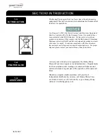
Страница 8: ...sposed as unsorted municipal waste For proper disposal please contact your nearest Henny Penny distributor As in any unit of food service equipment the Henny Penny Pressure Fryer does require care and maintenance Requirements for the maintenance and cleaning are contained in this manual and must become a regular part of the operation of the unit at all times Should you require outside assistance c...

Страница 9: ...ates a personal injury type hazard NOTICE is used to highlight especially important information CAUTION used without the safety alert symbol indicates a potentially hazardous situation which if not avoided may result in property damage CAUTION used with the safety alert symbol indicates a potentially hazardous situation which if not avoided could result in minor or moderate injury WARNING indicate...

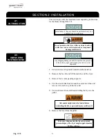
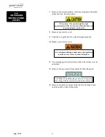
Страница 10: ...he presence of the delivery agent and signed prior to his or her departure 1 Cut and remove the plastic bands from the main box 2 Remove the box lid and lift the main box off the fryer 3 Remove four corner packing supports 4 Cut the stretch film from around the carrier rack box and remove it from the top of the fryer lid 5 Cut and remove the metal bands holding the fryer to the pallet 6 Remove the...

Страница 11: ... accessories from inside the filter drain pan 13 Remove the protective paper from the fryer cabinet Clean exterior surface with a damp cloth 2 2 UNPACKING INSTRUCTIONS CONT Do not drop The counterweights weigh approximately 18 lbs 8 1 kg each Handle with care or personal injury could result To avoid personal injury and assure safe operation of unit rear service cover must be in place The fittings ...

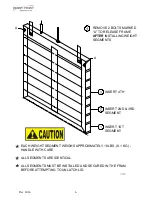
Страница 12: ... PADS 2 TYPICAL BOTH SIDES PRY OFF RAIL EITHER SIDE PROP UP A RAMP FOR EACH CASTER ON THE SELECTED SIDE REMOVE REAR COVER WEIGHT SEGMENTS MUST BE INSTALLED PER INSTRUCTION CONTAINED THEREIN BEFORE ATTEMPTING TO UNLATCH LID REMOVE THE ACCESSORIES FROM THE DRAIN PAN NOTE THE FITTINGS FOR GAS LINE ARE HERE REMOVE THE WEIGHTS FROM THE PALLET ...

Страница 13: ...NSTALLING WEIGHT SEGMENTS INSERT 4TH INSERT 2ND 3RD SEGMENT INSERT 1ST SEGMENT EACH WEIGHT SEGMENT WEIGHS APPROXIMATELY 18 LBS 8 1 KG HANDLE WITH CARE ALL SEGMENTS ARE IDENTICAL ALL SEGMENTS MUST BE INSTALLED AND SECURED IN THE FRAM BEFORE ATTEMPTING TO UNLATCH LID ...

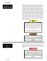
Страница 14: ...TIONS CAN RESULT IN SHORTENING OVERFLOWING THE FRYPOT WHICH COULD CAUSE SERIOUS BURNS PERSONALINJURY FIREAND OR PROPERTY DAMAGE The proper location of the fryer is very important for operation speed and convenience Choose a location which provides easy loading and unloading without interfering with the final assembly of food orders Operators have found that frying from raw to finish and holding th...

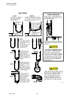
Страница 15: ...s in excess of 1 2 PSIG 3 45 KPA 34 47 mbar 2 5 VENTILATION OF FRYER 2 6 GAS SUPPLY 2 7 GAS PIPING The fryer should be located with provision for venting into adequate exhaust hood or ventilation system This is essential to permit efficient removal of the flue gases and frying odors Special precaution must be taken in designing an exhaust canopy to avoid interference with the operation of the frye...

Страница 16: ...nit and the flexible gas line disconnected This will allow better access to all sides of the fryer The gas line and cable restraint must be reconnected once the cleaning or servicing is complete 2 7 GAS PIPING CONT Provisions should be made for moving the fryer for cleaning and servicing This may be accomplished by 1 Installing a manual gas shut off valve and disconnect union or 2 Installing a hea...

Страница 17: ...t on all moveable gas fryers I bolt is to be secured to the building using acceptable building contruction practices DRY WALL CONSTRUCTION Secure I bolt to a building stud DO NOT attach to dry wall only Also locate the I bolt at teh same height as the gas service Preferred installation is approximately six inches to either side of service Cable restraint must be at least six inches shorter than fl...

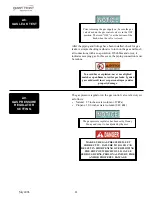
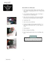
Страница 18: ...E SURE GAS PRESSURE IS SET CORRECTLY FAILURE TO DO SO CAN RESULT IN SHORTENING OVERFLOWING THE FRYPOT WHICH COULD CAUSE SERIOUS BURNS PERSONAL INJURY FIRE AND OR PROPERTY DAMAGE 2 8 GAS LEAK TEST 2 9 GAS PRESSURE REGULATOR SETTING After the piping and fittings have been installed check for gas leaks A simple checking method is to turn on the gas and brush all connections with a soap solution If bu...

Страница 19: ...ose on the pressure tap fitting and the other end on the manometer as shown in Figure 3 4 Turn the fryer ON 5 Allow the fryer to reach full burn 6 The pressure reading on the manometer should be 3 5 of water column for Natural gas and 10 of water column for LP gas 7 Turn the fryer off 8 Remove the pressure tap fitting 9 Place the pipe plug back into the valve or the fitting on the valve Notify a q...

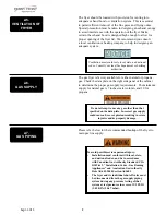
Страница 20: ...l circuit breaker which will disconnect all ungrounded unearthed conductors The main power switch on this appliance does not disconnect all line conductors 2 10 ELECTRICAL REQUIREMENTS The gas fryer requires 120 volt single phase 60 Hertz 10 amp 3 wire grounded earthed service or 230 volt single phase 50 Hertz service The 120 volt gas fryer is factory equipped with a grounded earthed cord and plug...

Страница 21: ...AY FILTER ONLY WHEN SHORTENING IS BELOW 275 F 135 C BRUSH ALL CRACKLINGS FROM FRYPOT SURFACES AND THE COLD ZONE DURING THE FILTERING PROCESS MAKE SURE THE FRYER IS LEVEL BE CERTAIN THE SHORTENING IS NEVER ABOVE THE UPPER FRYPOT LEVEL FILL LINE BE CERTAIN THAT THE GAS CONTROL VALVE AND BURNERS ARE PROPERLY ADJUSTED GAS UNITS ONLY USE RECOMMENDED PRODUCT LOAD SIZE FOR ADDITIONAL INFORMATION ON THESE...

Страница 22: ...ction for the frypot in the event an operator inadvertently drains the shortening from the frypot while the main switch is in the COOK position the switch is designed to automatically shut off the heat when the drain valve is opened SHORTENING MIXING SYSTEM A shortening mixing capability to help ensure shortening is properly mixed to prevent an accumulation of moisture and hence boiling action in ...

Страница 23: ... SWITCH Senses the flow of air coming from the blower if the airflow is reduced below a set amount the switch cuts power to the gas control valve which shuts down the burners BLOWER Adds the proper amount of air into the burner tubes so an efficient combustion takes place and also pulls the flue gases out to the flue AIR VALVE Pumps air into the shortening periodically to keep the shortening at a ...

Страница 24: ... 3 1 4 Flashes when the shortening temperature is not at the proper temperature for cooking product 3 1 5 Lights when the shortening temperature is 5 F 3 C below 3 1 6 INFO Press to display the following fryer information and status a The temperature of the shortening b The temperature setpoint c The number of Cook Cycles until Filter Lockout if turned on d If a Change Shortening function is enabl...

Страница 25: ...ated with each product selection button the menu card strip is located behind the decal 3 1 12 Product Select Buttons Are used to select the product for cooking to use them to start Cooking Cycles see Special Program Mode section 3 1 13 COOK PUMP Switch A 3 way switch with a center OFF position turn the switch to the COOK position to operate the fryer turn the switch to the PUMP position to operat...

Страница 26: ...19 April 2003 14 1 2 3 4 5 6 7 8 9 13 11 12 10 COOK OFF PUMP ...

Страница 27: ...flashes in the display 5 Press the to change the month 6 Press PROG and CS 2 SET DATE shows in the display with the date flashing 7 Press to change the date 8 Press PROG and CS 3 SET YEAR shows in the display along with the year flashing 9 Press to change the year 10 Press PROG and CS 4 SET HOUR shows in the display with the hour and AM or PM flashing 11 Press to change the hour and AM PM setting ...

Страница 28: ...aylight Saving Time adjustment DST activated on the last Sunday in March DST deactivated on the last Sunday in October 16 Press PROG and CS 8 BEGIN NEW DAY shows in display along with 3 00AM This setting indicates the time of day that statistics start accumulating for a new day If set to 3 00AM for example then late night cook cycles and filter operations from midnight to 3 00AM Tuesday morning ar...

Страница 29: ... the frypot level indicators on the rear of the frypot See photo below Failure to follow these instructions could result in a fire and or damage to the fryer When using solid shortening it is recommended to melt the shortening on an outside heating source before placing it in the frypots The burner tubes must be completely submerged in shortening Fire or damage to the frypot could result To avoid ...

Страница 30: ...position is to be avoided on small loads because of insufficient oil coverage With bigger loads the top rack has good oil coverage because the volume of product on the lower racks raises the overall oil level 3 6 PRODUCT RACKING RECOMMENDATIONS Load Type 4 3 2 1 Cooking ONE rack 2 head load 4 3 2 0000000000000 1 Cooking THREE rack 6 head load 4 3 0000000000000 2 0000000000000 1 0000000000000 Cooki...

Страница 31: ...fryer and each time the fryer is brought from a cold or shut down condition DO NOT OVERLOAD OR PLACE PRODUCT WITH EXTREME MOISTURE CONTENT INTO THE RACKS 20 LBS 9 0 KG IS THE MAXIMUM AMOUNT OF PRODUCT PER FRYPOT FAILURE TO FOLLOW THESE INSTRUCTIONS CAN RESULT IN SHORTENING OVERFLOWING THE FRYPOT WHICH COULD CAUSE SERIOUS BURNS PERSONAL INJURY FIRE AND OR PROPERTY DAMAGE DO NOT STIR THE SHORTENING ...

Страница 32: ...r five seconds The display shows EXIT MELT 1 YES 2 NO Press 1 button to exit melt In the event of a power failure no attempt should be made to operate the fryer The fryer is equipped with an automatic ignition system and cannot be operated without electrical power A different product can be selected during the first min ute of cooking in case the wrong product button was pressed To check the short...

Страница 33: ... the COOK PUMP switch is turned back on IS POT FILLED shows in the display followed by 1 YES 2 NO If shortening is at the proper level in the frypot press 1 but ton and the controls start a normal heating process If shortening is NOT at the proper level press the 2 button and TURN OFF UNTIL FILLED scrolls through the display Turn the COOK PUMP switch to the OFF position fill frypot to the proper l...

Страница 34: ...IRE AND OR PROPERTY DAMAGE COULD RESULT Drain the shortening at 275 F 135 C or less The higher temperatures cause cracklings to burn on the steel frypot surfaces after the shortening has drained 1 To protect the shortening when the fryer is not in immediate use the fryer should be put into the Idle Mode 2 Frying breaded products requires filtering to keep the short ening clean The shortening shoul...

Страница 35: ...d from sides and bottom of frypot as shortening drains Use straight brush to push cracklings through drain opening in bottom of frypot if necessary and to clean between the burner tubes and the frypot wall DRAIN CLEANOUT SMALL WHITE ROD BRUSH SHORTENING STIRRER 3 9 FILTERING INSTRUCTIONS CONT ONLY FILTER WHEN THE SHORTENING TEMPERATURE IS LESS THAN 275 F 135 C FAILURE TO DO SO CAN RESULT IN SHOREN...

Страница 36: ... fitting b Make sure the hose nozzle is pointed down into the bottom of the frypot and filter valve is in closed position Move the power pump switch to the PUMP position Hold nozzle carefully to avoid excessive splashing BRUSH ALL CRACKLINGS FROM FRYPOT SURFACES AND THE COLD ZONE DURING THE FILTERING PROCESS FAILURE TO DO SO CAN RESULT IN SHORTENING OVERFLOWING THE FRYPOT WHICH COULD CAUSE SERIOUS...

Страница 37: ...e and raise the fitting end of hose high for a minute to allow the remaining shortening in the hose to drain into the frypot 5 Turn COOK PUMP switch to PUMP 6 When all shortening has been pumped into frypot turn COOK PUMP switch to OFF 3 9 FILTERING INSTRUCTIONS CONT ONLY CONNECT AND DISCONNECT THE FILTER RINSE HOSE WHEN THE MAIN POWER SWITCH IS IN THE OFF POSITION ALSO USE A DRY CLOTH OR GLOVE TO...

Страница 38: ...lide the screens into a clean filter envelope 12 Fold the corners in and then double fold the open end 13 Clamp the envelope in place with the two filter retaining clips 14 Replace the crumb catcher screen on top of the filter paper Screw on the standpipe assembly 15 Place complete filter screen assembly back into filter drain pan and slide pan back into place beneath the fryer 16 Connect the filt...

Страница 39: ...the COOK PUMP switch to COOK position The burner will light until shortening reaches a preset temperature 5 Press desired product button after temperature is displayed on front of control panel TO SHUT DOWN BURNER 1 Turn POWER PUMP switch to the OFF position 2 Rotate gas control valve knob to the OFF position This fryer is equipped with a grounded earthed cord and plug for your protection against ...

Страница 40: ...as before every change of shortening the frypot should be thoroughly cleaned as follows 1 Turn the COOK PUMP switch to OFF and unplug unit from wall receptacle 2 If hot shortening is present in the frypot it must be drained by slowly pulling the drain handle out towards you 3 Close the drain valve and discard the shortening 4 Remove the racks and carrier from lid and tilt lid back so that the lid ...

Страница 41: ...p of the fryer Always wear chemical splash goggles or face shield and protective rubber gloves when cleaning the frypot as the cleaning solution is highly alkaline Avoid splashing or other contact of the solution with your eyes or skin Severe burns and possible blindness will result Carefully read the instructions on the cleaner If solution comes in contact with your eyes rinse thoroughly with coo...

Страница 42: ... install under fryer 16 Refill the fryer with fresh shortening Make sure the inside of the frypot the drain valve opening and all parts that come in contact with the new shortening are as dry as possible 3 12 CLEANING THE FRYPOT CONT 3 14 REGULAR MAINTENANCE As in all food service equipment the Henny Penny open fryer does require care and proper maintenance The table below provides a summary of sc...

Страница 43: ... to avoid electrical shock Depending on the breading location and conditions within the kitchen area the dilution box may need to be cleaned more often CHECKING CLEANING DILUTION BOX MONTHLY Cleaning the dilution box helps to ensure the unit operates efficiently and with few failures 1 Make sure unit is off and close and lock the lid 2 Unscrew the wingnut on the lower left back access panel of the...

Страница 44: ...s with cover removed 3 15 PREVENTIVE MAINTENANCE CONT If lid becomes difficult to operate stop using the fryer and call for service Cables need replaced INSPECT COUNTER WEIGHT CABLES ANNUALLY Henny Penny 8 head fryers use two cables in the counter weight mechanism that helps in the raising and lowering of the lid Cables should be visually inspected yearly either as part of a planned maintenance pr...

Страница 45: ...es have cracks in the jacket missing pieces in the jacket or other obvious signs of wear call for service to have both cables replaced NOT OK REPLACE Cracks in jacket and obvious signs of wear OK No signs of cracking or wear 3 15 PREVENTIVE MAINTENANCE CONT ...

Страница 46: ...eft and right rollers CLEANING BLOWER WHEEL ANNUALLY The blower wheel must be cleaned annually to ensure the unit operates efficiently and without failures 1 Make sure unit is off and close and lock the lid 2 Remove the back shroud of the unit 3 Remove the hose from the blower housing by sliding blower tube out of the bracket See photo at left 4 Clean the fins of the blower wheel using a brush or ...

Страница 47: ...ing the rest of the product The preload cycle always runs without pressure which always regulates to the Step 1 cook temperature Press to set a preload time or press PROG if no preload is desired 6 Press and release PROG and 1 COOK TIME shows in the display along with the preset time Press to change the time The time shows in minutes and seconds Press and hold the buttons and the time will jump by...

Страница 48: ...rm type on the right side of the display TIME SHAKE STIR ADD and LID can be set by pressing An alarm sounds and alarm type flashes prompting the operator to shake the basket stir the product or add product If TIME is selected the time remaining flashes in the display If LID is selected CLOSE LID flashes in the display The timer countdown is paused until the lid is closed and timer button is presse...

Страница 49: ...etting and slows down at temperatures below this setting Press and release to change this value Or to use the cooking setpoint temperature as the load compensation reference point press until STEP X and TEMP flashes in the display Now for example if the cooking temperature is 350 the timer speeds up when the shortening temperature is above 350 and slows down when the temperature is below 350 GO TO...

Страница 50: ...u location on the controller to another location preset the controls to factory settings or erase products and all their values 1 Press and hold PROG for one second until PROG shows in the display followed by ENTER CODE 2 Enter code 1 2 3 SELECT PRODUCT PRESS PROG scrolls across the display followed by DOWN FOR OPTIONS 3 Press and OPTION followed by 1 COPY A PROD shows in display Press again each ...

Страница 51: ...ny button for 20 seconds The controller displays X CANCELED X and exits the copy process In this case no changes are made ERASING On the Select Prog Product step press OPTIONS followed by 1 COPY A PROD shows in display Press three more times to reach the Erase All option 2 ERASE A PROD erases a single product 3 PRESET A PROD sets factory settings 4 ERASE ALL Press PROG to select the presently disp...

Страница 52: ... code change SP 16 Usage code change SP 17 Change shortening A Cook Cycles SP 18 Change shortening B Hours 1 Press and hold PROG for 5 seconds until L 2 and LEVEL 2 followed by SP PROG and ENTER CODE show in the display 2 Enter code 1 2 3 and SP 1 TEMP UNITS show in the display To exit from the Special Program Mode at any time press and hold PROG button for 2 seconds or to roll back to previous se...

Страница 53: ...f the display When INIT starts flashing on the left side of the display release When DONE shows on the display the initialization is complete and the controls now have factory preset parameters AUDIO VOLUME SP 4 The volume of the speaker can be adjusted a Follow steps 1 and 2 above b Press PROG 3 times SP 4 and AUDIO VOLUME flash on the display along with the volume value c Press to adjust the spe...

Страница 54: ...oggle from NO to YES or vice versa d With YES in the display the Idle Mode is enabled Press and release PROG SP 7A and IDLE SETPT TEMP show in the display along with the preset temperature The type of shortening being used in the cooker determines the amount of heat applied during the Melt Cycle If the controls are set to the solid setting less heat is applied to the shortening than if the control...

Страница 55: ...eeds filtering The Filter Tracking must be enabled to program the number of Cook Cycles between filtering procedures See Filter Cycles paragraph 3 16 a Follow steps 1 and 2 above b Press and release PROG until SP 8 and FILTER TRACKING ENABLED flash on the display along with 1 OFF c To enable the filter tracking press to toggle the display from 1 OFF to 2 MIXED or 3 GLOBAL d If 2 MIXED is selected ...

Страница 56: ...of the display shows a digit 1 to 99 Press to set the desired amount of Cook Cycles between filters j Press PROG and SP 8B shows in the display followed by LOCKOUT ENABLED and YES or NO Press and release to choose YES or NO k Press PROG and SP 8C shows in the display followed by LOCKOUT HEAT OIL and a temperature preset at 300ºF 149ºC When a filter lockout occurs the fryer heats up to this set tem...

Страница 57: ...oked then Filter Suggested shows in the display The numbers of loads can be set by pressing o Press PROG and SP 8F shows in the display followed by LOCKOUT ENABLED Press to choose YES or NO p Press PROG and SP 8G shows in the display followed by SP 8G LOCKOUT HEAT OIL and a shortening temperature when reached allows the operator to filter Example LOCKOUT HEAT OIL 300F means the display shows FILTE...

Страница 58: ...b Press PROG until SP 10 and CLEAN OUT MINUTES show in display along with the preset minutes c Press to change the number of minutes up to 99 CLEAN OUT TEMPERATURE SP 11 This allows you to set the temperature of the Clean Out Mode a Follow steps 1 and 2 above b Press PROG until SP 11 and CLEAN OUT TNP show in display along with the set temperature c Press to change the temperature up to 195 F 91 C...

Страница 59: ...NFO and CANCELED shows in display then reverts back to SP 15 and CHANGE MGR CODE 1 YES Then the above steps can be repeated USAGE CODE CHANGE SP 16 This allows the operator to change the usage code factory set at 1 2 3 used to reset the usage data in the Information Mode a Follow steps 1 and 2 above b Press PROG until SP 16 and CHANGE USG CODE 1 YES show in display along with USAGE c Press 1 butto...

Страница 60: ...OURS SP 18 This mode allows the operator to set the number of power on hours between shortening changes These hours are not only cooking time but the total time the fryer is on When the set numbers of hours are reached the control displays CHANGE OIL SOON This mode is just a reminder and cooking can continue a Follow steps 1 and 2 above b Press PROG until SP 18 and CHANGE OIL B HOURS show in displ...

Страница 61: ...this data was manually reset 5 INPA VHDSF PM PM provides test of fryer inputs 6 OUTP shows the state of heater and pressure 7 OIL TMP temperature of shortening 8 CPU TMP temperature of PC board 9 ANALOG status of controller s a to d converter 1 E LOG error code log Press and 1A date time NOW show in display This is the present date and time Press and if a error was recorded 1B date time and error ...

Страница 62: ...t and time rem STEP 1 325 F 6 47 Actual shortening temp deg below load comp avg present stretch time real secs ck sec 313 FLC 12 1 06 FUNCTION DISPLAY EX Day this data was recorded for TUE APR 30 Number of Hours Minutes the fryer was on TUE ONHRS13 45 Number of times shortening was filtered that day TUE FILTERED 3 Total number of Cook Cycles that day TUE TOTAL CK 38 Cook Cycles for product 1 TUE C...

Страница 63: ...ge information RESET USG ENTER CODE 5 INP A_CVHDSFPM PM Press to view the status of components and inputs If the input signal is detected an identifying letter is displayed see below If the signal is not detected _ is displayed With the COOK PUMP switch in the COOK position and all inputs detected H_ P_ A_CVHDSFPM PM shows in display See below for definition of codes See chart to the left of the p...

Страница 64: ...e fan output F shows in display with the flashing When ignition modules are on I shows in the display If ignition modules are off I_ shows in display If controls sense a problem with an ignition module I shows in the display with flashing If heat is on H shows in display If heat is off H_ shows in display If controls sense a problem with the heat output H shows in display with the flashing If pres...

Страница 65: ...tput PC board Press PROG to continue onto the OIL TMP reading 7 OIL TMP This step shows the present peanut oil temperature The display shows 7 OIL TMP temp Press PROG to continue onto the CPU TMP reading 8 CPU TMP This step shows the present PC board temperature Press PROG to continue onto the ANALOG reading 9 ANALOG 1 2 86V This step displays the present status of any channel of the controller s ...

Страница 66: ...eaking Place full capacity product in frypot when using fresh shortening Remove shipping spacer see Unpacking Instructions Section Check programming Reverse or replace lid gasket Shortening not heating Gas valve knob turned to the OFF position Drain valve open High temperature limit tripped Make sure gas control valve knob is turned to the ON position Close drain valve Reset high temperature limit...

Страница 67: ...d return to normal if E 5 persists have control panel replaced E 6 Temperature probe failure Turn switch to OFF position then back to ON if the display shows E 6 the temperature probe should be checked once the probe is repaired or replaced the controls should return to normal if E 6 persists have control panel replaced E 41 Programming failure Turn switch to OFF position then back to ON if displa...

Страница 68: ...s call Henny Penny s Service Department E 20D Right module failure Press the timer button to try the ignition process again and if E 20D persists call Henny Penny s Service Department E 20E Both modules failure Press the timer button to try the ignition process again and if E 20E persists call Henny Penny s Service Department E 20F Left module no flame sense Press the timer button to try the ignit...

Страница 69: ...25 H Henny Penny Corp Eaton Ohio 45320 Revised 3 20 14 Henny Penny Corporation P O Box 60 Eaton OH 45320 1 937 456 8400 1 937 456 8402 Fax Toll free in USA 1 800 417 8417 1 800 417 8434 Fax www hennypenny com ...

Отзывы: