background image

Pressure Transmitters 050D series 


Operating Instructions 


- English - V1.0


PN-TI118-EN-14-1/16 

Hengesbach GmbH & Co. KG  

·

  Schimmelbuschstr. 17 

·

  40699 Erkrath  

· 

 Tel. +49 (0) 21 04 / 30 32-0  

·

  Fax +49 (0) 21 04 / 30 32-22   

· 

www.hengesbach.com


12


Repair, return and guarantee 

12.1


Repair 

If the transmitter shows any sign of  malfunction, please always contact  the manufacturer  first. The manufacturer will help you over the 
telephone with all further actions that are necessary and may be able to suggest a solution for the problem. Often, the devices are merely 
incorrectly set and seem to be malfunctioning because of such incorrect settings. 

However, if a device has a definite fault, please return it to the manufacturer. The transmitter does not contain any parts, which can be 
repaired by the user. The manufacturer's QA department will ensure that your device is repaired as quickly as possible or, if the device is 
still under warranty, will provide you with a free replacement device. 


Please do not attempt to repair the transmitter on your own accord. You may loose your warranty entitlement 
and possibly make the fault worse.


12.2


Return 

If you return a device to us, please observe the following notes: 

Secure the measuring cell against all forms of contact 

Pack the device in transport-proof outer packaging 

Pack the electronic components in ESD-compliant outer packaging 

Include a precise description of the transmitter fault with the returned device 

Tell us what you would like us to do with the returned item if applicable 

Use the 

product accompaniment form

 included in the scope of delivery when returning the device


The manufacturer's returns address is: 

Hengesbach Prozessmesstechnik GmbH & Co. KG


[email protected]

 / 

[email protected]


Schimmelbuschstr. 17


www.hengesbach.com


40699 Erkrath


Tel.:


+49 (0) 2104 3032-0 

GERMANY


Fax.:


+49 (0) 2104 3032-22 


12.3


Guarantee 

The manufacturer warrants all manufactured products for a period of 1 year from delivery. Devices, which develop a fault or fail entirely 
during this period, will be repaired or replaced by the manufacturer. Please contact the manufacturer before you make your complaint in 
order to discuss further actions, as this will ensure the quick and smooth processing of your request. 


Faults, which are due to incorrect handling, incorrect installation or other improper handling of the product, will 
not be regarded as warranty cases. In such instances, the manufacturer will prepare a report for each individual 
case. 

Please  also  observe  the  return  notes  in  the  event  of  warranty  processing.  The  manufacturer  may  not  be  able  to  tell  who  should  be 
responsible for a device, which has become damaged during its return transport to the manufacturer because it was incorrectly packed. 
Therefore, in the worst case scenario, you may have to bear the damage yourself. For this reason we ask you to always make sure that you 
choose a safe means of transport packaging and pay special attention to the membrane of the measuring cell, as this is the one item, which 
gets damaged most often. 

Содержание 050D Series

Страница 1: ...PN TI118 EN 14 1 1 Hengesbach GmbH Co KG Schimmelbuschstr 17 40699 Erkrath Tel 49 0 21 04 30 32 0 Fax 49 0 21 04 30 32 22 www hengesbach com ...

Страница 2: ..._______ _____________________________________________________________________________________________________ _____________________________________________________________________________________________________ _____________________________________________________________________________________________________ ______________________________________________________________________________________...

Страница 3: ...the measuring range full adjustment 4 3 Restoring factory settings 4 4 Reading the status LED in measuring mode 5 Opening the outer packaging 6 Identifying the device 7 Assembly information 8 The connection and operating elements in the device head 9 Electrical connection 9 1 Operating voltage range 9 2 Types of electrical connection 9 3 Connection diagram for normal measuring mode 9 4 Calibration...

Страница 4: ...tion Electrostatic danger Electrostatic danger points to the fact that the device or its components could suffer irreparable damage from electrostatic discharge Magnetically sensitive Magnetically sensitive points to the fact that placement of the device in electromagnetic fields can subject its operation to a negative influence Caution heat Caution heat is a warning of personal injury from burns ...

Страница 5: ... of flashing is c 2Hz The status LED flashes red green alternately The status LED in the device head flashes red green alternately The frequency of flashing of every colour is c 6Hz key This symbol represents the key in the device head with the following designation key This symbol represents the key in the device head with the following designation and keys This symbol represents the combination ...

Страница 6: ...osive atmosphere Please read these operating instructions carefully before commissioning the devices If you have questions please contact the manufacturer s technical department The manufacturer can be contacted under the following address Hengesbach Prozessmesstechnik GmbH Co KG Schimmelbuschstr 17 40699 Erkrath GERMANY Tel 49 0 2104 3032 0 Fax 49 0 2104 3032 22 www hengesbach com info hengesbach...

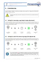
Страница 7: ...n release the key the transmitter has saved the pressure value as the new measuring range begin and issues a 4mA signal Hold the key depressed Status LED extinguishes Initialisation phase 5s Status LED illuminates green Release the key 4 2 Setting the end of the measuring range full adjustment Use the full adjustment to set the transmitter measuring range end To this end apply the desired under pr...

Страница 8: ... operation The following flash patterns and their significance are explained here Status LED illuminates green The current process pressure is located within the operating thresholds set for the transmitter The output current is proportional to the measuring value The transmitter is in its optimum transducer mode Status LED flashes green The current process pressure is located outside the operatin...

Страница 9: ...of the shipment until its commissioning and the check of the moisture proof status of the screw connections Check that the goods are correct undamaged and complete Compare the details on the delivery note with the contents of the shipment received Please notify the manufacturer of any discrepancies 6 Identifying the device The following figures show a transmitter type plate example and the meaning...

Страница 10: ...move the protective cover from the measuring cell during the assembly preparations Only remove the cover shortly before installing the transmitter Make sure that you don t touch the membrane during the installation The device manufacturer recommends that device openings such as ventilation openings should point downwards during the installation if possible This way in the event that process media ...

Страница 11: ...ess calibrator can be connected to the connection terminal without needing to disconnect the power supply to control Additionally potential equalisation to the control unit can be made via the terminal Slide switch The slide switch can be used to switch the transmitter from normal measuring operation and the calibration function It enables power supply of the device from a further source Status LE...

Страница 12: ...nsmitter will not be damaged as its connection terminals are secured against voltage reversal 9 2 Types of electrical connection Depending on the connection variant which you have ordered the transmitter can come in one of four possible configurations The electrical connection of the device is contained in the device designation The four possible variants are listed in the following Cable screw co...

Страница 13: ...following schematic Connect the power supply with the transmitter via the terminals 1 and 2 Observe and comply with the permissible voltage range of 12 30V DC Ensure maintenance of the correct polarity the voltage reversal does not cause any damage but it will not commence measurement operation The pressure value determined by the transmitter is depicted in the supply loop with a current proportio...

Страница 14: ...t be able to provide a minimum current of 22mA In this configuration the transmitter is supplied by a mobile instrument and depicts its measured value through a proportional current in the calibrator loop The supply via the terminals 1 and 2 is not in operation it need not be disconnected The slide switch does not establish a galvanic isolation between the two circuits The calibration function is ...

Страница 15: ... of the measuring value If the reference cable is used the ventilation tube must also be free from foreign objects The transmitters are fully encapsuled and therefore have no dead spaces However especially during the cleaning process major heating up with subsequent cooling down processes can result in a vacuum inside the device This effect will be reduced to a minimum due to the small dead space ...

Страница 16: ... with the returned device Tell us what you would like us to do with the returned item if applicable Use the product accompaniment form included in the scope of delivery when returning the device The manufacturer s returns address is Hengesbach Prozessmesstechnik GmbH Co KG service hengesbach com info hengesbach com Schimmelbuschstr 17 www hengesbach com 40699 Erkrath Tel 49 0 2104 3032 0 GERMANY F...

Страница 17: ...not perform as expected please check the following points before contacting the manufacturer Fault Possible causes Check correction The device does not start or no current is flowing in the loop the status LED remains out The voltage of the power supply is reversed or incorrectly connected Make sure that the power supply is connected correctly The power supply is not switched on Use a voltmeter to...

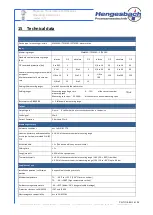
Страница 18: ...g span span 25 100 of the sensor s nominal measuring span Burst pressure DIN16086 4 fold nominal measuring range Output Output signal 2 wire 4 to 20mA with a test circuit connection in the device Fault signal 22mA Current limitation 3 8mA and 21mA Measuring accuracy Reference conditions acc to DIN IEC 770 Linearity hysteresis and repeatability acc to the limit point method DIN IEC 770 0 2 of the s...

Страница 19: ...EHEDG type EL ASEPTIC CLASS I certified connection system PZM with press screw M38x1 5 and elastomer sealing Process seal EPM FDA temperature range 20 150 C Process seal FPM FDA temperature range 40 200 C Materials Field housing lid CrNiSt 1 4301 304 Housing seal FPM Viton Pressure compensation element polyamide Process connection connection adapter CrNiSt 1 4404 304 Process membrane CrNiSt 1 4435...

Отзывы: