2.6 SAFETY INSTRUCTIONS
For your safety, before connecting the power source to the line, closely follow these instructions:
•
An adequate two-pole switch must be inserted before the main outlet; this switch must be equip-
ped with time-delay fuses;
•
The connection with ground must be made with a two-pole plug compatible with the above men-
tioned socket;
•
When working in a confined space, the power source must be kept outside the welding area and the
ground cable should be fixed to the workpiece. Never work in a damp or wet area, in these conditions.
•
Do not use damaged input or welding cables
•
The welding torch should never be pointed at the operator’s or at other persons’ body;
•
The power source must never be operated without its panels; this could cause serious injury to the
operator and could damage the equipment.
3.0
INTRODUCTION
MATERIAL TO WELD
GAS CYLINDER
WIRE
Mild steel
Argon + CO2 cylinder or
CO2 cylinder
Copper coated mild steel wire spool.
For no gas welding use flux-cored wire spool
Stainless steel
Argon cylinder
Stainless steel wire spool.
Aluminum
Argon cylinder
Aluminum wire spool
This manual was edited to give some indications on the operation
of the welder and was thought to offer information for its practical
and safe use. Its purpose is not to teach welding techniques. All
suggestions are indicative and intended to be only guide lines.
To ensure that your welder is in good condition, inspect it carefully
when you remove it from its packing taking care to ascertain
that the cabinet or the stocked accessories are not damaged.
Your welder is capable of daily activity metal fabrication and
maintenance. Its simplicity and versatility and its excellent
welding characteristic are the product of the most up to date
inverter technology. This welding inverter offers the welder the
ability to create precise arc characteristics and at the same time
reduce consumption of energy with respect to the welders based
on a traditional transformer.
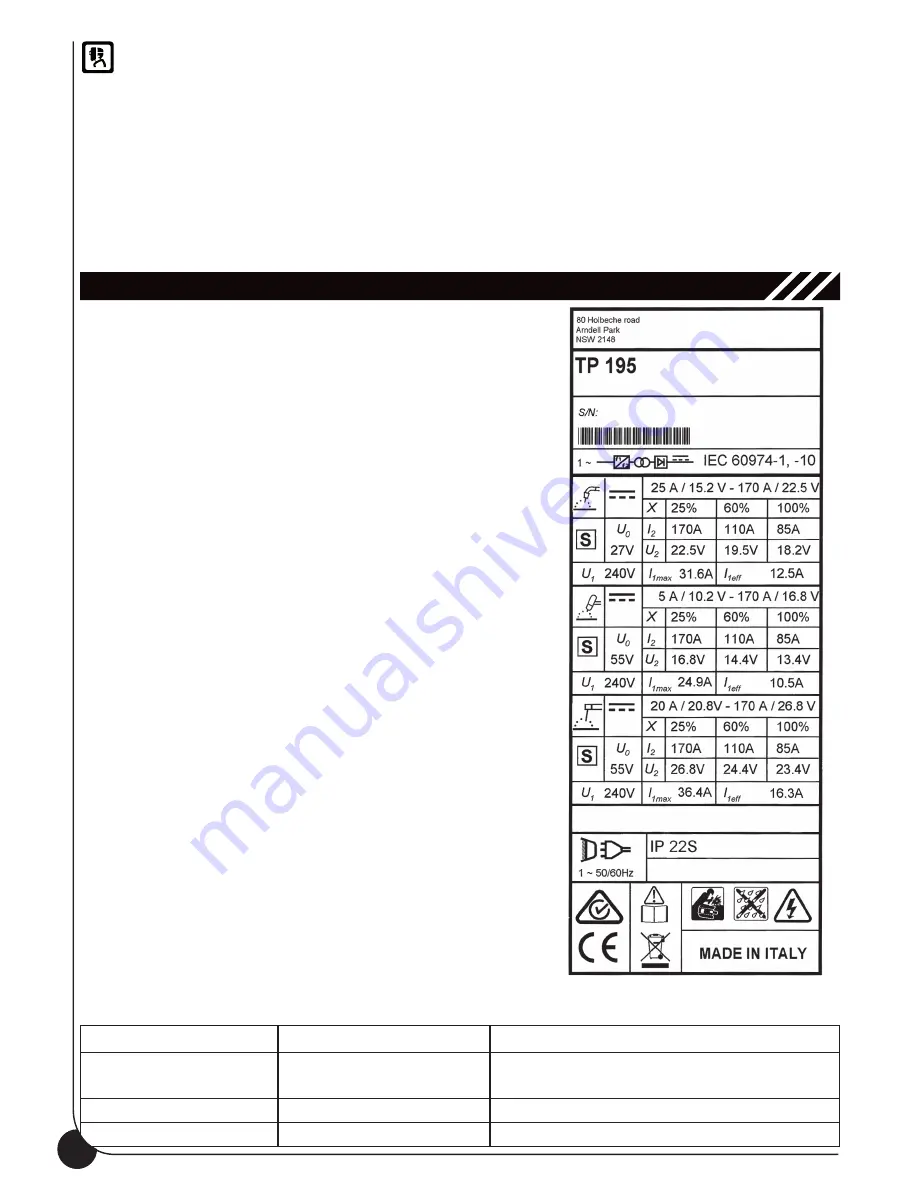
Respect the duty cycle of the welder making reference to the
technical data label on the welder’s back. Duty cycle is given
as percentage on a 10 minute time. During this period of time
the unit can be used at the rated duty cycle. Exceeding the rated
duty cycle may cause overheating or welder damage.
Welder’s basic specifications (Figure 3)
Welding Wire Selection:
This welder can work with Aluminum wire 0,8÷1,0 diameter,
solid steel wire 0,6÷1,0 diameter and stainless steel wire
0,8÷1,0 diameter (Gas Welding) and with flux core wires
0,8÷1,0 diameter (No Gas Welding).
Feed Rolls:
groove 0,6-0,8mm for wires 0,6÷0,8mm
groove 1,0-1,2mm for wires 1,0mm
Feed rolls for Aluminum, U-groove 0,8-1,0mm for wires 0,8mm
Gas Selection
According to the material to be welded and to the wire you are
going to use, select the shielding gas. The table below can give
you some useful indications:
Figure 3
6
Содержание TP 195
Страница 1: ...TP 195 OPERATING MANUAL ...
Страница 2: ......
Страница 15: ...15 Figure 9 ...
Страница 16: ...13 0 WIRING DIAGRAM 16 ...
Страница 17: ...17 ...
Страница 18: ...18 ...
Страница 19: ...19 ...
Страница 20: ...77611864 ...


