7.1.5 GAS CYLINDER AND REGULATOR CONNECTION
WARNING: Cylinders are highly pressurized. Handle with care. Serious accidents
can result from improper handling or misuse of compressed gas cylinders. Do not
drop the cylinder, knock it over, expose it to excessive heat, flames or sparks. Do not
strike it against other cylinders.
The gas cylinder (not supplied) should be located at the rear of the welder, in a well ventilated area and
securely fixed to the work bench or to the wall to insure that it will not fall.For safety, and economy, ensure that
the regulator is fully closed, (turned counter-clockwise)when not welding and when installing or removing the
gas cylinder.
•
Turn the regulator adjustment knob counter-clock wise to ensure the valve is fully closed.
•
Install the gas regulator on the gas cylinder, tighten the connecting nut firmly to insure against gas
leakage.
•
Connect the gas hose to the gas regulator.
•
Open the cylinder valve, then set the gas flow to approx. from 5 to 15l/min. on the regulator.
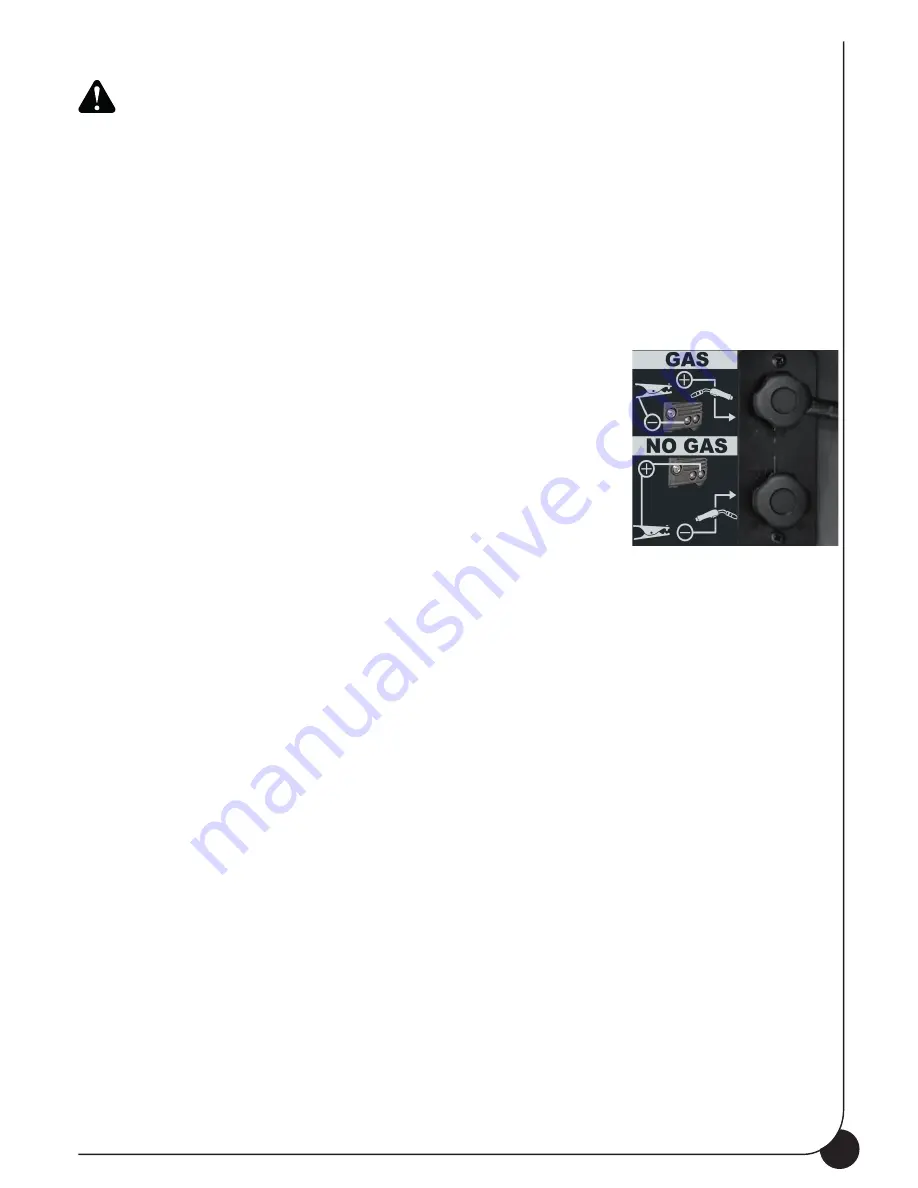
7.1.6 FLUXCORE WIRE WELDING, “FCAW”
•
Connect the ground cable to the positive terminal of the Polarity
Change Board inside the spool compartment.
•
Connect the working cable to the negative terminal of Polarity
Change Board inside the spool compartment.
7.1.7 MIG WELDING, “GMAW”
•
Connect the ground cable to the negative terminal on the Polarity
Change Board inside the spool compartment.
•
Connect the working cable to the positive terminal of the Polarity
Change Board inside the spool compartment.
7.2 MIG / NO GAS MANUAL WELDING
Before connecting the unit to the mains, verify that all the accessories are correctly installed and mounted
for electric welding (torch, wire spool etc ...).
•
Select Manual MIG Welding function with the Selector Switch (6) on the front panel.
•
Switch the unit ON thru the ON/OFF switch (13) on the back side of the unit.
•
Press the torch trigger to load the wire.
•
Set the welding parameters:
1.
Wire feed speed: use Left Knob (8) to adjust the wire speed expressed in mm on the Left
Display (4).
2.
Arc voltage: use the Right Knob (7) to adjust arc voltage value (no load) from 12V to 26V.
Refer to the Setting Chart on the access panel to get a guideline on the welding parameters set-
ting. (Figure 9 on page 15)
•
Bring the torch close to the work piece and press the trigger.
1.
Wire feeder Slope-Up Time (Min. to Max. speed transition time), adjustable with the poten-
tiometer located inside the access panel (16).
2.
At the end of the Slope-Up Time, the wire feed speed reaches the value adjusted with the
Left knob (8).
•
To stop welding, release the trigger. The arc stays ON accordingly to the set B.B.T. (Burn back time).
B.B.T. is the amount of time that the weld output continues after the wire stops feeding. It prevents
the wire from sticking in the puddle and prepares the end of the wire for the following arc start.
7.3 SYNERGIC MIG WELDING
•
Select the wire type and thickness (MIG Syn) thru the Selector Switch (6) on the front panel.
•
MIG Synergy functions permits the operator to get the optimal welding parameters simply setting
the thickness of the material to be welded (Right Knob -7-). Once this parameter is set, the syner-
gic function automatically adjusts the welding voltage and the wire speed allowing the operator to
balance this last value if necessary with the Left Knob (8).
•
Switch the unit ON thru the ON/OFF switch (13) on the back side of the unit.
•
Press the torch trigger to load the wire and check that the gas is flowing from the welding torch.
•
Select the thickness of the material to be welded using the Right Knob (7).
Figure 8
11
Содержание TP 195
Страница 1: ...TP 195 OPERATING MANUAL ...
Страница 2: ......
Страница 15: ...15 Figure 9 ...
Страница 16: ...13 0 WIRING DIAGRAM 16 ...
Страница 17: ...17 ...
Страница 18: ...18 ...
Страница 19: ...19 ...
Страница 20: ...77611864 ...


