SYSTEM FILL AND STARTUP
5. COMMISSIONING
2
Flow Direction
1
3
5.0. Pressure Test and Clean Collector Loop
Before filling the collector loop with Dyn-O-Flo HD solution, pressure test the collector loop to check for soldering leaks. Remove the expansion
tank and cap off the exposed port, then fill the collector loop with water using the site hose and pressurize up to mains pressure 60 – 80 psig.
The filling station can also be used.
Monitor the pressure gauge for drops in pressure, inspect all joints. Turn the collector loop pump on to clean out residue; a 2% TSP solution
can be used. Fully drain the system to ensure correct glycol concentration upon final fill.
5.1. Calculate System Fluid Volume and Necessary Glycol Concentration
Find the total fluid capacity by adding in the volume of the collectors, HPAK and supply and return lines. With the total volume, use the
equation below to find out necessary gallons of glycol. Glycol concentration should be 40 – 60% for proper inhibitor concentration, regardless
of required freeze protection. A higher concentration than is required for freeze protection is recommended in case of errors in fluid
calculation.
5.2. Fill System
The system can be filled easily with a filling pump from Heliodyne or manually. Consult
the manual with the filling pump for operation. Take care to use mineral spring water or
good quality tap water and only fill system when collector is cold. See installation notes
at the end of this manual for water requirements. Air vents or bleed vents at the high
points in the system help rid the system of air during filling only. If using any type of
automatic air vent, close vent after filling is complete as vents are not suitable for glycol
systems, or systems without continuously replaced fluids.
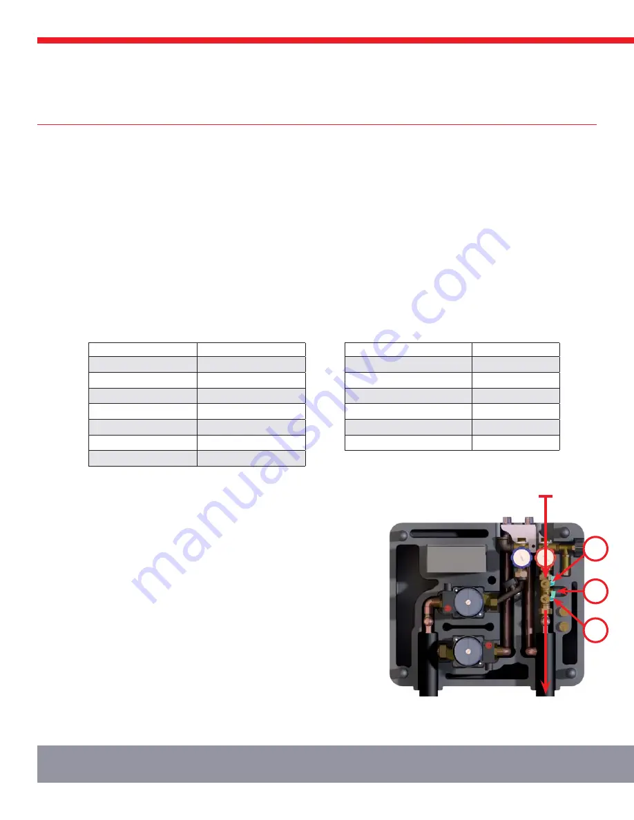
For use with a pump, connect pump supply hose to position 3 at right, and return hose
to position 2. Turn 1 so slot is horizontal, forcing return fluid out of 2. Turn on pump
to begin filling. After fluid begins to return back into tank from 2, close off valve at 2
and open 1. System will pressurize rapidly; monitor gauge and close off valve at 3 when
system reaches 40 – 60 psi. Turn off pump. Close off any bleed or air vents and run
system throughout the day. Check after a day cycle to ensure the cold pressure of the
system is at around 30 psig when cold. If further pressurization is necessary, hook up
pump supply to 3, turn pump on, open valve and pressurize back up.
For manual fill, pour in proper glycol and water mixture with a funnel into the top unused
header connection of Gobi. Pressurize with house water using the valve at position 3;
follow pressure guidelines as above. Hose nipples are provided, pre-set into the foam
next to the fill valve.
SYSTEM COMPONENT
FLUID CAPACITY (GAL.)
GOBI 406 001 & 002
0.75
GOBI 408 001 & 002
0.83
GOBI 410 001 & 002
0.95
HPAK 016 000 & 001
0.80
HPAK 024 000 & 001
0.95
HPAK 032 000 & 001
1.00
HPAK 048 000 & 001
1.25
ASTM B88 COPPER TUBING
GALLONS / 100’
Type M 1/2” (5/8” OD)
1.32
Type M 3/4” (7/8” OD)
2.68
Type M 1” (1-1/8” OD)
4.54
Type M 1-1/4” (1-3/8” OD)
6.80
Type M 1-1/2” (1-5/8” OD)
9.51
Type M 2” (2-1/8” OD)
16.5
Gallons of Dyn-O-Flo HD = Desired Concentration (%) * Total System Fluid (gal.) / 100


