13
Design and Installation
Typical Components of a GutterMelt
®
SR system include:
•
GutterMelt SR heating cable
•
Activation device, automatic or manual
•
Power connect Kit(s) and End Seal Kit(s)
•
Roof Attachment Clips with fasteners and/or adhesive
•
Downspout Hanger Kits
•
Relay Panel or Contactor Panel for larger projects
Necessary Information:
•
Length of eaves, gutters, and downspout drains to be heat traced
•
Distance from eave edge to inside the outside wall
•
Voltage Available
•
Type of Roof covering material
Draw a sketch of the area where GutterMelt
®
SR snow melt will be
installed. The sketch should show all measurements and dimensions
in order to determine the area to be snow melted. Determine the
location for the GutterMelt
®
SR temperature/moisture sensor or other
activation device.
Note: GutterMelt
®
SR is designed for snow melt applications
and to provide a path for water to exit the roof, gutter, and
downspout drain.
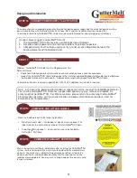
STEP 1 PLAN THE LAYOUT
Note: Make certain to plan for the movement of the water created
when GutterMelt
®
SR melts snow and/or ice from the roof, gutters
and/or downspouts to an acceptable refreeze location.
Annual Maintenance
Remove all debris from gutters and downspouts.
Verify the integrity of the GutterMelt
®
SR by conducting a visual inspection
and checking the insulation between the heating elements and the ground
shield with a Megohmmeter. Record the value if it exceeds 20 megohms
for GutterMelt
®
SR Cable. If damage to GutterMelt
®
SR Heating Cable is
discovered, and/or the Megohmmeter test yields a megohms reading less
than 20, then correctly repair or replace the GutterMelt
®
SR with new cable
prior to energizing.
Warning: Always disconnect power to GutterMelt® SR and its
activators prior to handling, replacing and/or servicing.
MEASURE AND
RECORD
RESISTANCE
Содержание Gutter Melt SR
Страница 2: ...2...


