


GAS CONNECTION
PART 7: GAS CONNECTION
(CONTINUED)
B. GAS PIPING
1. Run the gas supply line in accordance with all applicable codes.
2. Locate and install manual shutoff valves in accordance with state and local requirements.
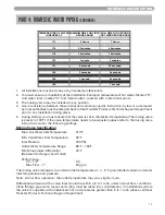
C. GAS TABLE
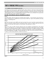
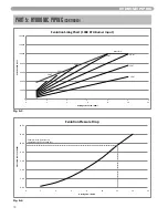
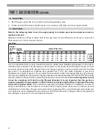
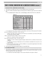
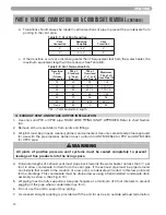
Refer to the following table to size the supply piping to minimize pressure drop between meter or
regulator and unit.
Maximum Capacity of Pipe in Cubic Feet of Gas per Hour for Gas Pressures of 0.5 psi or Less and a
Pressure Drop of 0.3 Inch water Column
Gas Table
It is recommended that a soapy solution be used to detect leaks. Bubbles will appear on the pipe to
indicate a leak is present. The gas piping must be sized for the proper flow and length of pipe, to avoid
excessive pressure drop. Both the gas meter and the gas regulator must be properly sized for the total
gas load. If you experience a pressure drop greater than 1" WC, the meter, regulator or gas line is
undersized or in need of service. You can attach a manometer to the incoming gas drip leg, by removing
the cap and installing the manometer. The gas pressure must remain between 3.5" WC and 14" WC during
stand-by (static) mode and while in operating (dynamic) mode at full output.
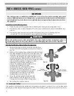
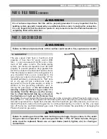
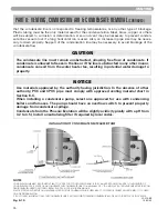
If an in-line regulator is used,
it must be a minimum of 10 feet from the Phoenix Evolution. It is very important that the gas line is
properly purged by the gas supplier or utility. Failure to properly purge the lines or improper line sizing,
will result in ignition failure.
This problem is especially noticeable in NEW LP installations and also in
empty tank situations. This can also occur when a utility company shuts off service to an area to provide
maintenance to their lines. The gas valve must not be replaced with a conventional gas valve under any
circumstances. As an additional service feature in the Phoenix Evolution, the gas valve in this appliance
has a flanged connection to the swirl plate and blower.
Nominal
Iron Pipe Internal
Length of Pipe (Feet)
Size
Diameter
(inches) (inches)
10
20
30
40
50
60
70
80
90
100
125
150
175
200
3/4
.824
278
190
152
130
115
105
96
90
84
79
72
64
59
55
BTU'S
1
1.049
520
350
285
245
215
195
180
170
160
150
130
120
110
100
PER
1 1/4
1.380
1,050
730
590
500
440
400
370
350
320
305
275
250
225
210
}
HOUR
1 1/2
1.610
1,600 1,100
890
760
670
610
560
530
490
460
410
380
350
320
x1,000
27
Содержание Phoenix Evolution
Страница 71: ...70 ...
Страница 72: ...71 ...
Страница 73: ...72 MAINTENANCE NOTES ...
Страница 74: ...73 MAINTENANCE NOTES ...
Страница 75: ...74 MAINTENANCE NOTES ...
Страница 76: ... 2009 Heat Transfer Products Inc www htproducts com LP 314 REV 12 21 09 ...


