background image

FIELD WIRING / GAS CONNECTION

PART 6: FIELD WIRING 

(CONTINUED)

PART 7: GAS CONNECTION

A. GAS SUPPLY

The gas supply shall have a maximum inlet
pressure of less than 14" water column (350
mm), ½ pound pressure (3.5 kPa), and a mini-
mum of 3.5" water column. The entire piping
system, gas meter and regulator must be sized
properly to prevent pressure drop greater than
0.5" WC as stated in the National Fuel Gas Code.
This information is listed on the rating plate. It is
very important that you are connected to the
type of gas as noted on the rating plate. "LP" for
liquefied petroleum, propane gas or, "Nat" natu-
ral or city gas. All gas connections must be
approved by the local gas supplier, or utility in
addition to the governing authority, prior to
turning the gas supply on. 

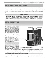
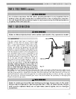
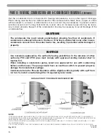
Do not remove the

reducing coupling attached to gas valve! It is
mandatory that this fitting is used for connec-
tion to a field fabricated drip leg as shown in
the illustration at right per the National Fuel
Gas Code.

You must ensure that the entire gas line to the connection at the Phoenix Evolution is no

smaller than ¾". Once all the inspections have been performed, the piping must be leak tested. If the
leak test requirement is a higher test pressure than the maximum gas inlet pressure, you must iso-
late the Phoenix Evolution from the gas line to continue leak testing. In order to do this, you must
turn off the factory and field-installed gas cocks. This will minimize the possibility of damaging the
Phoenix Evolution gas valve. 

WARNING

It is of extreme importance that this unit be properly grounded. It is very important that the
building system ground is inspected by a qualified electrician, prior to making this connection.
It is very important that the electrical power is only turned on when the Phoenix Evolution is
completely filled with cold water.

WARNING

Failure to follow all precautions in this section could result in fire, explosion or death!

UNION

DRIP LEG

Fig. 7-1

WARNING

Failure to isolate gas line while leak testing may damage the gas valve. In the event
the gas valve is exposed to a pressure greater than ½ PSI, 14" water column, the gas
valve must be replaced. Never use an open flame (match, lighter, etc.) to check gas
connections.

26

Содержание Phoenix Evolution

Страница 1: ...2009 Heat Transfer Products Inc Phoenix Evolution Water Heater Models PHE130 55 PHE199 55 PHE130 80 PHE199 80 PHE130 119 PHE199 119 A suffix of LP denotes propane and S denotes Solar Models SNHX denotes Solar Models without heat exchanger ...

Страница 2: ... s instructions If you cannot reach your gas supplier call the fire department Installation and service must be performed by a qualified installer service agency or the gas supplier If the information in this manual is not followed exactly a fire or explosion may result causing property damage personal injury or loss of life Do not store or use gasoline or other flammable vapors and liquids in the...

Страница 3: ...ief Valve for DHW B Domestic Hot Water Expansion Tank C Domestic Water Piping D Phoenix Evolution Piping E Mixing Valve Installation F Auxiliary Piping Part 5 Hydronic Piping 16 22 A Hydronic Piping Module B Pressure Relief Valve for the Hydronic System C Hydronic Expansion Tank and Make Up Water D Hydronic Heating Module System Piping E Hydronic Heating Module Output Part 6 Field Wiring 23 26 A F...

Страница 4: ... D Programming the System Setting E System Setting Program Navigation F Phoenix Evolution Control Status Menu Part 10 Start up Procedure 47 53 A Fill and Purge DHW B Fill and Purge Hydronic Heating Loop C Purge Air from Hydronic Heating Module D Evolution Pump Control to Assist in Purging Air from the System Loops E Programming the Total System Control F Operating Instructions F Maintenance Part 1...

Страница 5: ...touch any electric switch do not use any phone in your building Immediately call your gas supplier from a neighbor s phone Follow the gas suppliers instructions If you cannot reach your gas supplier call the fire department SPECIAL ATTENTION BOXES The following defined terms are used throughout this manual to bring attention to the presence of hazards of various risk levels or to important informa...

Страница 6: ... Heating System and The Domestic Hot Water System This is accomplished through sensors that provide feedback to the control that monitors inputs such as Outdoor Temperature Tank Temperature Heating Module Outlet Temperature thus allowing accurate control over the entire system You may choose to use the factory default settings or you can re program the control system parameters to help provide sys...

Страница 7: ... line if a long horizontal run is used Also an increase in the pipe size may be necessary to drain properly Support of the condensate line may be necessary to avoid blockage of the condensate flow 9 Spark ignition The burner flame is ignited by applying a high voltage to the system spark electrode This causes a spark from electrode to ground 10 Outdoor Sensor The outdoor sensor will monitor the ou...

Страница 8: ...NCE ZERO CLEARANCE 24 MINIMUM CLEARANCE CLEARANCE 12 MINIMUM PART 3 PREPARE WATER HEATER LOCATION CONTINUED n WARNING Failure to keep the unit area clear and free of combustible materials gasoline and other flammable liquids and vapors can result in severe personal injury death or substantial property damage n WARNING The space must be provided with combustion ventilation air openings correctly si...

Страница 9: ...ion Intake and exhaust must terminate near each other and may be vented vertically through the roof or through a side wall The intake and exhaust venting methods are detailed in the Venting Section Do not attempt to install the Phoenix Evolution using any other venting means Be sure to locate the Phoenix Evolution so that the air intake and exhaust vent piping can be routed through the building an...

Страница 10: ...an existing gas water heater the following steps must be followed with each appliance remaining connected to the com mon venting system placed in operation while the other appliances remaining connected to the common venting system are not in operation a Seal any unused openings in the common venting system b Visually inspect the venting system for proper size and horizontal pitch and determine th...

Страница 11: ...y hard moderately hard or hard based on its hardness number The minerals in the water will precipitate out when the water is heated and will cause accelerated lime and scale accumulation on a heat transfer surface If the hardness of the water exceeds the maximum level of 7 grains per gallon water should be softened to a hardness level no lower than 5 grains per gallon Water softened as low as 0 to...

Страница 12: ...at will affect the efficiency and service life of the unit The Evolution Heating Module is designed with highly efficient plate type heat exchanger on the hydroninc closed loop side that transfers energy from one side of the plate to the other side Water quality can also greatly impact the long term operation of this heat exchanger so it is important to check water prior to operating the unit Fail...

Страница 13: ...ge line in a manner that will prevent possibility of severe burns or property damage should the valve discharge Discharge line must be as short as possible and be the same size as the valve discharge connection throughout its entire length Discharge line must pitch downward from the valve and terminate at least 6 above the floor drain where any discharge will be clearly visible The discharge line ...

Страница 14: ... temperature by mixing the hot and cold water from the discharge outlet or mixed outlet port This device alone will not protect the user from scald ing temperature Point of use devices must be installed to protect user from scalding temperatures Use only point of use mixing valves that are rated under the approved ASSE 1016 standard To install and set up the mixing valve follow the pre installatio...

Страница 15: ...et Temperature 39 F Inlet Pressure 200 PSI Outlet Water Temperature Range 85 F 150 F Min Temperature Differential 20 F Between Hot Supply and Outlet Performance CV 1 2 3 3 Max Flow 1 24 gpm The mixing valve maintains a constant outlet temperature of 5 F given limited variation of water inlet temperature and pressure Note At low flow operation the outlet temperature may vary slightly more Different...

Страница 16: ...tlet temperature with a thermometer Using the groove on the top of the cover provided to fit over adjustment nut adjust the knob counter clockwise to increase temperature and clockwise to decrease temperature as shown in Fig 4 2 3 Once the desired outlet temperature has been achieved refit the green top so that it snaps onto the body of the mixing valve 4 Re connect the outdoor sensor F AUXILIARY ...

Страница 17: ...ncy low mass boilers B PRESSURE RELIEF VALVE FOR THE HYDRONIC SYSTEM The pressure relief valve supplied is designed to relieve pressure greater than 30 PSI The Hydronic Heating Module is designed to withstand pressure up to 150 PSI If you are changing the pressure relief valve for a higher pressure you must make sure that the system components are designed for the higher pressure The relief valve ...

Страница 18: ...ycol solution in the system piping Example 50 by volume glycol solution expands 4 8 in volume for the temperature increase from 32 F to 180 F while water expands 3 with the same temperature rise Listed below are the basic steps that will help guide you through the installation of the Hydronic Heating Module to the system piping 1 Connect the system return marked Return 2 Connect the system supply ...

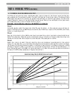
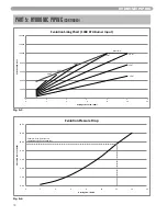
Страница 19: ... 1 Using the graphs select the input rate of the Phoenix Evolution In this example we would have to select a minimum input of 199K Phoenix Evolution the 130K max output is 100 000 BTU which falls below our operating point Step 2 Next go to the chart for the 199K burner input and select the point of operation where the BTU and Delta T line intersect Mark the point on the chart and go to bottom of c...

Страница 20: ... Example At 12 GPM there is approximately 10 Ft of head loss 0 20000 40000 60000 80000 100000 120000 140000 0 2 4 6 8 10 12 Evolution BTU Input Heating System Flow GPM Evolution Sizing Chart 130K BTU Burner Input 25 ȴT 20 ȴT 15 ȴT 10 ȴT Max Limit 30 ȴT 35 ȴT 40 ȴT HYDRONIC PIPING 19 Fig 5 4 Fig 5 3 PART 5 HYDRONIC PIPING CONTINUED ...

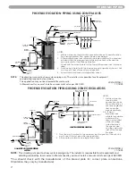
Страница 21: ...AN 50 FEET FROM THE WATER HEATER TO THE FAN COIL IN THE AIR HANDLER 2 MASSACHUSETTS STATE PLUMBING CODE REQUIRES AN ELECTRONICALLY TIMED CIRCULATOR PUMP REQUIRED TO ACTIVATE EVERY SIX HOURS FOR 60 SECONDS THIS CIRCULATOR IS REQUIRED TO BE BRONZE OR STAINLESS 3 ALL WATER PIPING MUST BE INSULATED 4 YOU MUST INSTALL A VACUUM RELIEF VALVE PER 248 CMR NOTES 1 Minimum pipe size should match connection s...

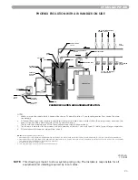
Страница 22: ... to the maximum input capacity of the unit Unit must have 10 feet of pipe after gas regulator 4 All circulators shall have an integral flow check NOTE This drawing is meant to show system piping only The installer is responsible for all equipment and detailing required by local codes In Massachusetts you must install a vacuum relief valve per 248 CMR You should check with the manufacturer of the b...

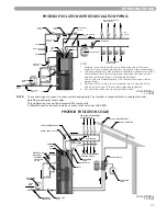
Страница 23: ...UPPLY LP 314 PIPING 4 11 20 09 NOTE These drawings are meant to show system piping only The installer is responsible for all equipment and detailing required by local codes This application may not be allowed in Massachusetts In Massachusetts you must install a vacuum relief valve per 248 CMR PHOENIX EVOLUTION WITH RECIRCULATION PIPING PHOENIX EVOLUTION SOLAR NOTES 1 Minimum pipe size should match...

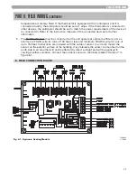
Страница 24: ...he 120 volts supplied an external motor starter will be required 3 Please note that the solar pump connectors on the field connection board are not functional at this time D LOW VOLTAGE WIRING 1 Make all low voltage connections to the terminal strip located on the field connection board shown in Figure 6 1 as outlined below 2 The Room Thermostat should be connected to the terminals marked T STAT s...

Страница 25: ...r to the instruction manuals of the connected devices for further information 3 The Outdoor Sensor must be connected for the unit operate at optimum efficiency Use a minimum 22 AWG wire for runs of 100 feet or less and minimum 18 AWG wire for runs of up to 150 feet Instructions are included with the outdoor sensor to correctly mount the sensor on the exterior surface of the building It is preferab...

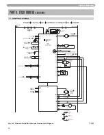
Страница 26: ...FIELD WIRING PART 6 FIELD WIRING CONTINUED Fig 6 2 Phoenix Evolution Internal Connection Diagram LP 314 L 11 03 09 F INTERNAL WIRING 25 ...

Страница 27: ...gas line to the connection at the Phoenix Evolution is no smaller than Once all the inspections have been performed the piping must be leak tested If the leak test requirement is a higher test pressure than the maximum gas inlet pressure you must iso late the Phoenix Evolution from the gas line to continue leak testing In order to do this you must turn off the factory and field installed gas cocks...

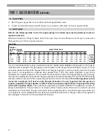
Страница 28: ...essure must remain between 3 5 WC and 14 WC during stand by static mode and while in operating dynamic mode at full output If an in line regulator is used it must be a minimum of 10 feet from the Phoenix Evolution It is very important that the gas line is properly purged by the gas supplier or utility Failure to properly purge the lines or improper line sizing will result in ignition failure This ...

Страница 29: ...ficially approved conversion kit and instructions supplied by Heat Transfer Products Inc Failure to do so could result in death or serious injury 6 9 9 6 6 87 2 9 9 7 5277 867 5 127 I IRU DQ UHDVRQ WKH WKURWWOH QHHGV WR EH DGMXVWHG LW LV YHU LPSRUWDQW WKDW D 20 867 21 1 5 EH XVHG WR HQVXUH VDIH DQG SURSHU RSHUDWLRQ 7XUQ WKH DGMXVWHU WR WKH WR LQFUHDVH WKH JDV VXSSO 7KLV DGMXVWPHQW ZLOO DIIHFW WKH ...

Страница 30: ...nting must be ULC S636 Certified IPEX is an approved manufacturer in Canada supplying vent material listed to ULC S636 PVC DWV ANSI ASTM D2665 CPVC schedule 40 80 ANSI ASTM F441 Pipe cement primer PVC ANSI ASTM D2564 IPEX System 636 Cements Primers CPVC ANSI ASTM F493 n WARNING This vent system will operate with a positive pressure in the pipe Do not connect vent connectors serving appliances vent...

Страница 31: ...ntioned equipment unless the 4 foot horizontal distance is maintained g When adjacent to a public walkway locate exit terminal at least 7 feet above grade h Do not locate the exhaust directly under roof overhangs to prevent icicles from forming i Provide 4 feet clearance from the inside corner of vertical walls chimneys etc as well as horizontal corners created by roof overhangs 2 Determine air in...

Страница 32: ...g Note Exhaust must extend out 1 foot There should be no more than 2 vents and 2 intakes then a space of 36 to the next set of vents Note There must be a minimum of 36 spacing between every 2 kit grouping Multiple V Series Vents Fig 8 3 Multiple Stainless Steel Horizontal Vent Kit Installation Front View Fig 8 1 Multiple Vents Fig 8 4 Multiple Concentric Vent Spacing Vertical Fig 8 5 Multiple Conc...

Страница 33: ... length is 46 feet which is well below the maximum of 85 feet c The intake air vent pipe and the exhaust vent are intended to penetrate the same wall or roof of the building d Effort should be made to keep a minimum difference in equivalent length between the intake air vent pipe and the exhaust vent 3 The minimum combined equivalent length is 16 equivalent feet F LONGER VENT RUNS 1 The maximum co...

Страница 34: ...ust pipe must be piped around an obstacle that results in the creation of a low point condensate will collect in this low point and form a blockage This condensate must be drained away using a field installed condensate drain assembly as shown See Fig 8 10 5 All piping must be fully supported Use pipe hangers at a minimum of 4 foot intervals to prevent sagging of the pipe where condensate may form...

Страница 35: ...r smoke from a cigarette 6 After it has been determined that each appliance remaining connected to common venting system properly vents when tested as outlined return doors windows exhaust fans fireplace dampers and any other gas burning appliance to their previous condition of use 7 Any improper operation of the common venting system should be corrected so the installation conforms with the Natio...

Страница 36: ... absence of other authority PVC and CPVC pipe must comply with approved venting material chart in Section 8 C When installing a condensate pump select one approved for use with condensing boilers and furnaces The pump should have an overflow switch to prevent property damage from condensate spillage Condensate from the Phoenix Evolution will be slightly acidic typically with a pH from 3 2 to 4 5 I...

Страница 37: ...CAL PIPING ALL HORIZONTAL SUPPORT BRACKETS MUST BE USED ON LEFT SIDE VIEW BLOCKAGE TO PREVENT CONDENSATE NOTE EXTENDED VIEW RUNS WHEN TRANSITIONING TO A LARGER DIAMETER MUST ALWAYS TAKE PLACE IN A VERTICAL POSITION A NOTE When placing support brackets on vent piping the first bracket must be within 1 foot of the appliance and the balance at 4 foot invervals on the vent pipe J DIAGRAMS FOR VENTING ...

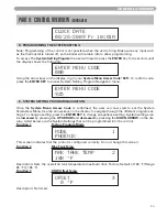
Страница 38: ...o change the value Repeat until the correct code is entered Press the ENTER key to accept the code entered If the code is correct the readout will change to the appropriate screen If the programming code is not accepted the readout will continue to display as shown above The ENTER key is also used to enable a parameter for editing After the user navigates to the desired parameter the user would ho...

Страница 39: ...iance to its optimum performance CENTRAL HEATING 140 F Function Allows the user to adjust the central heating designed supply set point from 50 F to 170 F Factory Default 140 F HEATING DELTA T 20 F Function Allows the user to adjust the heating system designed delta T from 5 F to 30 F Factory Default 20 F DHW SET POINT 119 F Function Allows the user to adjust the DHW Set Point from 95 F to 180 F F...

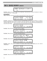
Страница 40: ...down arrow key once and the letter will disappear Press the Enter key to save the new setting CLOCK HOUR 08 28 2009 Fr 10 01A Function Allows the user to adjust the Hour Setting CLOCK MINUTE 08 28 2009 Fr 10 01A Function Allows the user to adjust the Minute Setting CLOCK DAY OF WEEK 08 28 2009 Fr 10 01A Function Allows the user to adjust the Day of Week displayed CLOCK DATE MODE 08 28 2009 Fr 10 0...

Страница 41: ...EM SETTING PROGRAM NAVIGATION Once the System Menu Access Code is confirmed the user can now start to set the System Parameters Menu Use the arrows keys on the display to navigate through the different program set tings To change a setting press the ENTER KEY to change an appliance setting System settings can be increased by pressing the UP ARROW and decreased by pressing the DOWN ARROW on the dis...

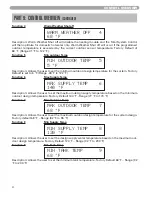
Страница 42: ...x Supply Temp MAX SUPPLY TEMP 6 140 F Description Allows the user to set the maximum design supply temperature based on the minimum outdoor design temperature Factory Default 140 F Range 77 F to 170 F Function 7 Max Outdoor Temp MAX OUTDOOR TEMP 7 68 F Description Allows the user to set the maximum outdoor design temperature for the system design Factory default 68 F Range 32 F to 95 F Function 8 ...

Страница 43: ...an outdoor sensor is open or shorted Note This error does not stop the appliance from running Factory Default ON Selection ON OFF PHOEN ON Function 13 Error System Senor ERROR SYSTEM SENS 13 ON Description Allows the user to set the control to display and error message if the system sensor is open or shorted Note This error does not stop the appliance from running Factory Default ON Selection ON O...

Страница 44: ...escription This parameter sets the 2 right digits of the amount of run hours for the next service reminder Function 18 TELEPHONE 18 000 000 0000 Description Allows the user to input a telephone number that will be displayed when maintenance is required F PHOENIX EVOLUTION CONTROL STATUS MENU The Phoenix Evolution Controller also has the ability to review the status of the system To access the stat...

Страница 45: ... ON in place of the temperature Note To ensure a properly installed sensor be sure that this temperature reading is similar to the current outdoor conditions Press the key once DHW SETING 119 F TANK TARGET 160 F This screen displays on the top line the current domestic hot water temperature set point entered in appliance settings The bottom line displays the current tank target temperature Note Th...

Страница 46: ...fault encountered if one has occurred and the bottom line will display the date and time that the fault occurred Press the key once FAULT HISTORY 20 08 28 2009 Fr 5 19A This screen displays the second oldest lockout fault the boiler controller had The top line will alter nate between the words FAULT HISTORY and the actual fault encountered if one has occurred and the bottom line will display the d...

Страница 47: ...Press the key once FAULT HISTORY 70 08 28 2009 5 19A This screen displays the seventh oldest lockout fault the boiler controller had The top line will alter nate between the words FAULT HISTORY and the actual fault encountered if one has occurred and the bottom line will display the date and time that the fault occurred Press the key once FAULT HISTORY 80 08 28 2009 5 19A This screen displays the ...

Страница 48: ...tely call your gas supplier from a neighbor s phone Follow the gas suppliers instructions If you cannot reach your gas supplier call the fire department 3 Turn off gas shutoff valve located inside of the cabinet so that the handle is aligned with the gas pipe If the handle will not turn by hand don t try to repair it call a qualified service technician Force or attempted repair may result in a fir...

Страница 49: ...eat from the heated water from the domestic side of the system Operating pressure must never exceed the relief valve pressure setting of 30 psi c At initial fill and during start up and testing check system thoroughly for any leaks Repair all leaks before proceeding further 4 The system may have residual substances that could affect water chemistry After the system has been filled and leaked teste...

Страница 50: ...he Phoenix Evolution Note The Phoenix Evolution will fire the burn er and heat the water inside the storage tank to the domestic hot water temperature set point Press The display can show the temperature set point of the Phoenix Evolution Press the and Enter keys simultaneously and hold for 1 second The display will read SERVICE PUMP CH PUMP ON TIME The central Heating Pump will come on Run pump u...

Страница 51: ...lay to navigate through the Appliance Setting Program To change a setting press the ENTER key Appliance settings can be increased by pressing the UP ARROW and decreased by pressing the DOWN ARROW on the display Once a new value has been selected press enter to store the new value 6 In the first screen is the Central Heating value Enter the value for your designed hydronic heating supply temperatur...

Страница 52: ...performance The values below show the systems default and can be adjusted to optimize your systems performance 11 Press and hold enter for 4 seconds until you see the screen to enter the log in access code screen ENTER MENU CODE 000 12 Use the left and right arrow to move the blinking zero to the left and right Next using the up and down arrow keys on the display log in your access code of 925 to ...

Страница 53: ...ow to adjust to your designed temperature To store the new value press ENTER 17 Press the right arrow once to scroll to Function 8 MIN SUPPLY TEMP This function is the final step to setting your outdoor reset curve Enter the hydronic heating module minimum supply temperature value to which you designed your system To adjust the value press enter and the factory default of 120 F start to blink Use ...

Страница 54: ...nition trial will not occur immediately After a failed igni tion trial the blower must run for approximately 10 seconds to purge the system Therefore a time period of approximately 40 to 90 seconds will expire between each ignition trial If the burner lights during any one of these three ignition trials normal operation will resume If the burner lights and goes off in about 4 seconds check the pol...

Страница 55: ...ndication light and display a fault message in the format The alarm output will also be activated Most fault conditions will also cause the CH pump to run in an attempt to cool the heater 2 Note the fault message that is displayed and refer to Fault Code section for an explanation of the fault message along with several suggestions for corrective actions 3 Press the reset key to clear the fault an...

Страница 56: ... it Wiring errors may cause improper and dangerous operation Verify proper operation after servicing Outdoor Sensor 7250P 319 Outside Temperature F Resistance ohms 22 171800 13 129800 4 98930 5 76020 14 58880 23 45950 32 36130 41 28600 50 22800 59 18300 68 14770 77 12000 86 9804 95 8054 104 6652 113 5522 Water Temperature F Resistance ohms 32 32550 41 25340 50 19870 59 15700 68 12490 77 10000 86 8...

Страница 57: ...e Supply Sensor Vertical Pipe 2 Check the electrical connection to the thermistor on the outlet manifold check the wiring har ness If both are connected properly replace the control NOTE Verify the themistor values by referencing the Resistance Tables in Section 12 3 Replace themistor if necessary Fault Code ECS NOT CONNECTED PUMP OFF This display indicates that the main control board and the smal...

Страница 58: ...ndicates the status of the pump Remedy 1 Assure that the flue is not blocked 2 Check the switch wiring by applying a jumper in place of the switch If the code clears with the jumper in place REPLACE the flue switch and connect the wires to the new switch BEFORE run ning unit Fault Code LEO LOW WATER LEVEL LEO PUMP OFF This display indicates that there is a low water level in the main tank This cod...

Страница 59: ...f the message clears examine the wiring to the heating module and fan for shorts or grounds and repair as necessary 6 If message only occurs when the burner tries to light check gas valve for excessive current draw 7 If message is present with the low voltage harness disconnected from the 926 control board replace the 926 control board Fault Code F00 WATER HIGH TEMP F00 PUMP ON Description This di...

Страница 60: ...dicates that the top temperature sensor of the tank has failed This code indicates a serious safety issue and the unit will not restart until the sensor is replaced by a technician and push ing the RESET button on the display This situation is indicated by the red light on the display illu minating and the word LOCKOUT flashing on the display During this lockout fault the circulator pump will be o...

Страница 61: ...emperature of the tank is excessive If this code is accompa nied by the illuminated red FAULT light and LOCKOUT flashing on the display then this code indi cates that the temperature on the bottom sensor has exceeded 230 deg F and a serious safety issue exists The boiler will not restart until the cause of the excessive temperature is repaired by a tech nician and pushes the RESET button on the di...

Страница 62: ...he pushes the RESET button on the display The red light on the display illuminating and the word LOCKOUT flashing on the display During this lockout fault the pump will be on as indi cated on the second line of the display Remedy 1 Monitor the gas pressure to the unit while in operation 2 Assure that the flame is stable when lit 3 Check to see if the display readout changes from GAS VALVE ON to RU...

Страница 63: ...l has commanded it to run at The fan speed had been more than 30 faster or slower than the commanded speed for more than 10 seconds This code indicates a serious safety issue and the unit will not restart until the cause is determined by a technician and he pushes the RESET button on the display The red light on the display will illumi nate and the word LOCKOUT will be on the display During this l...

Страница 64: ...a qualified technician Remedy Control must be re programmed If programming does not solve problem control must be replaced Fault Code PP CONTROL PROGRAMED PP Description The control has been programmed by a technician or the factory After programming the control is left in a locked out mode Press the RESET key to begin use of the control Remedy Press S4 reset for at least 1 second ...

Страница 65: ... 23 34 53 46 19 1 2 7 3 8 14 1 2 5 14 46 46 PHE130 80 PHE199 80 80 23 34 72 61 20 1 2 8 3 8 15 1 2 6 13 61 64 1 2 PHE130 119 PHE199 119 119 27 37 74 65 3 4 20 1 2 8 3 8 15 1 2 6 14 1 4 65 3 4 66 1 2 PHOENIX EVOLUTION WATER HEATER SPECIFICATIONS MODEL GALLONS BTU S AIR INTAKE EXHAUST VENT SIZE WATER INLET OUTLET SIZE AUXILIARY CONN GAS LINE CONN SYSTEM RELIEF PIPE SIZE SHIPPING WEIGHT PHE130 55 PHE...

Страница 66: ...J K L M N O PHE130 80S PHE199 80S 80 23 34 72 61 38 1 2 26 37 24 31 1 4 64 1 2 64 1 2 10 1 4 10 1 4 PHE130 119S PHE199 119S 119 27 37 74 65 3 4 38 1 2 26 37 24 33 64 1 2 66 1 2 5 3 4 5 3 4 PHOENIX EVOLUTION SOLAR WATER HEATER SPECIFICATIONS MODEL GALLONS BTU S AIR INTAKE EXHAUST VENT SIZE WATER INLET OUTLET SIZE AUXILIARY CONN GAS LINE CONN SYSTEM RELIEF PIPE SIZE SHIPPING WEIGHT PHE130 80S PHE199...

Страница 67: ...7 N A CONDENSATE PLASTIC STRAIGHT 1 17 7100 121 7100P 121 CONDENSATE HOSE 1 18 7250 215 7250P 215 CONDENSATE HOSE CLAMP 2 19 T1500 VS210 THERMODISC FLUE ECO 210Σ 1 20 7250 154 7250P 154 HOSE BARB 1 4 X 10 32 1 21 S7100 246 S7100 247 7100P 264 7100P 265 55 80 GAL PLASTIC CABINET 199 GAL PLASTIC CABINET 1 22 S7100 250 7100P 266 CONTROL BOARD DISPLAY INCLUDES MEMBRANE DISPLAY BOARD PLASTIC SHELL AND ...

Страница 68: ...1 6 5 6 1 3 2 5 1 675 7 211 725 6 9 9 3 6 9 9 37 5 1 1 0 3 36 3 1 6 5 3 137 6 9 9 3 0 5 7 7 21 352 7 6 7 3 1 26 67 1 33 1 1370 137 675 7 2 3 1 7 5 5 7 752 6 7 LP 314 G REV 11 19 09 LP 314 H REV 12 14 09 7 0 12 3DUW 5HSODFHPHQW 3DUW HVFULSWLRQ HID XOW 4 7 3 7521 3 7 3 21752 2 5 3 2 9 17 35 6685 6 7 3 3 2 1 92 87 21 6 2 5 1 7 5 250 1 6 5 3 92 87 21 86720 5 211 7 21 2 5 1 3 3 1 7 50 1 2 1 3 3 1 7 50 ...

Страница 69: ...afe condition Refer to Venting Details in this manual for further venting instruction Gas Check gas piping test for gas leaks and signs of aging make sure all pipes are supported properly SYSTEM Visual Do a full visual inspection of all system components Functions Safeties Test all functions of the system Heat Safeties Temperatures Domestic Verify safe settings on water heater or Mixing Valve Temp...

Страница 70: ...ch brite to take oxides off of surface that may affect the performance Check the Spark Gap as referenced in the manual pg 59 for natural gas unit The LP units spark to the burner directly Water Pressure Switch Check operation check for signs of leakage replace if corroded SAFETIES Low Water Cut Off Check low water cut off by pulling lead off of probe you should see an FOU Fault code on the display...

Страница 71: ...70 ...

Страница 72: ...71 ...

Страница 73: ...72 MAINTENANCE NOTES ...

Страница 74: ...73 MAINTENANCE NOTES ...

Страница 75: ...74 MAINTENANCE NOTES ...

Страница 76: ... 2009 Heat Transfer Products Inc www htproducts com LP 314 REV 12 21 09 ...

Отзывы: