


34
TROUBLESHOOTING
If the furnace fails to operate check the following:
• Is the thermostat operating properly?
• Are the blower compartment door(s) in place?
• Is the furnace disconnect closed?
• Has the circuit breaker tripped or the control board fuse
burned open?
• Is the gas turned on?
• Are any manual reset switches open?
• Is the filter dirty or plugged?
• Is the flame sensor coated? (Remove and clean with
steel wool).
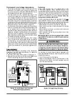
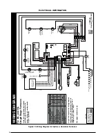
• Are all the LED’s on the furnace control board constantly
ON? If not, refer to Table 11 or the wiring diagram (Figure
19, page 30) to determine fault condition.
IMPORTANT NOTE: The furnace will lock out after 5
failed attempts for ignition and will try again every
hour if the call for heat remain
s.
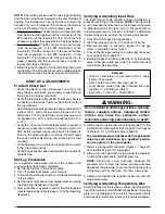
• If the inducer blower is operating and items above have
been verified, check the blower limit switch and reset
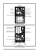
if necessary. See Figure 20 (page 35) for component
location.
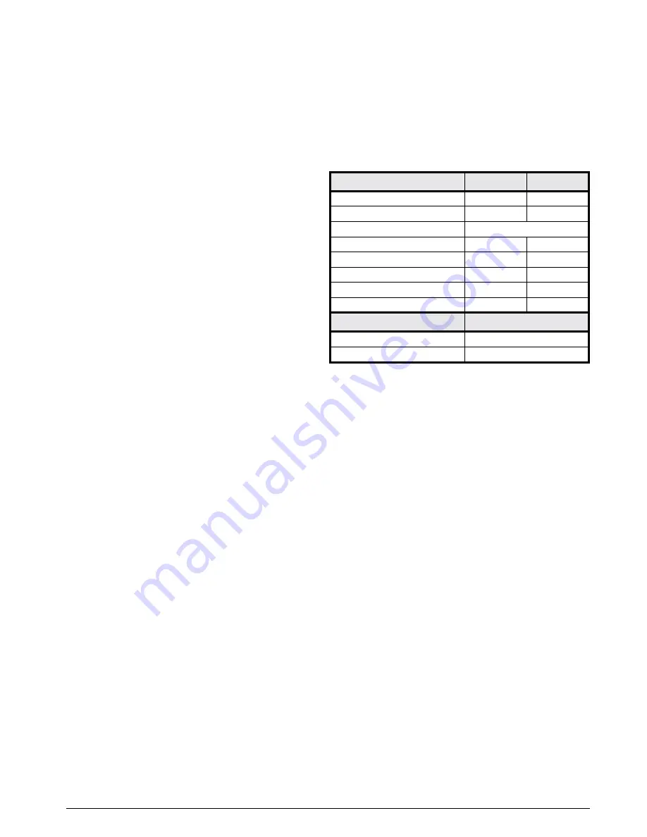
Diagnostic Description
Green LED
Red LED
Control Fault (No Power)
Off
Off
L1/Neutral Polarity Fault
Flash
Flash
1 Hour Lockout
Alternating Flash
Normal Operation
On
On
Pressure Switch Closed Fault
On
Flash
Pressure Switch Open Fault
Flash
On
Open Limit Switch Fault
Flash
Off
Motor Fault
On
Off
Diagnostic Description
Yellow LED
Low Flame Sensor Signal
Continuous Flash
Flame Present
On
Table 11. Control Board Fault Conditions
• If the furnace operates when the blower limit switch is
reset, contact a qualified service technician to identify
and repair the problem.
• If the furnace still doesn’t operate, check the flame
roll-out switch and reset if necessary. See Figure 20
for component location.
• If the furnace operates when the flame rollout switch is
reset, contact a qualified service technician to identify
and repair the problem.
FURNACE COMpONENTS
The descriptions below are various functional components that affect the operation and shutting down of this furnace.
Some of these components and their locations are shown in Figure 20 (page 35). If any component of the furnace must
be replaced, use only factory authorized replacement parts specified in the Replacement Parts List provided online.
Blower Limit Switch -
Prevents operation when blower is not operational.
Flame Sensor -
Verifies when a flame has carried over from the igniter to the opposite end burner. If no flame is
detected, the furnace will shut down within 4 seconds.
Flame Roll-Out Switch -
Verifies that the burner flames are drawn into the heat exchanger tubes. If the burner
flames are not properly drawn into the heat exchanger, the flame roll-out switch will close the gas valve and initiate
the shutdown cycle.
Gas Valve -
Controls the flow of gas to the burners. When the gas valve is energized it automatically opens and
regulates the gas pressure in the manifold.
Inducer Assembly -
Vents products of combustion to the outside.
Pressure Switch -
Verifies that the inducer is drawing the combustion gases through the heat exchanger. The
pressure switch prevents furnace operation with excessive flue blockage or improper inducer operation.
Supply Air Limit Switch -
Prevents the air temperature leaving the furnace from exceeding the maximum allowable
outlet air temperature.


