Heat Controller 80+ AFUE Скачать руководство пользователя страница 24

24

Fan Mode

•  When  the  thermostat  energizes  the 

G

 terminal for 

continuous fan (without calling for heat or cooling), the 
indoor fan is energized on the selected FAN speed.

•  If a call for cooling occurs during continuous fan, the 

blower will switch over to the selected COOL speed.

•  If the 

w

 terminal receives a call for heat during continuous 

fan, the blower will de energize.

•  A call for fan is ignored while in lockout.

MAINTENANCE

Proper maintenance is most important to achieve the best 

performance from a furnace. Follow these instructions for 

years of safe, trouble free operation.

ELECTRICAL SHOCK, FIRE OR EXPLOSION 

HAzARD

Failure to follow safety warnings exactly could 
result in serious injury or property damage.
Improper servicing could result in dangerous 
operation,  serious  injury,  death  or  property 
damage.
•  Before  servicing,  disconnect  all  electrical 

power to furnace.

•  When servicing controls, label all wires prior 

to disconnecting. Reconnect wires correctly.

•  Verify proper operation after servicing.”

 wARNING:

RISQUE DE CHOC ÉLECTRIQUE, D’INCENDIE 
OU D’EXPLOSION

Le  non-respect  des  avertissements  de  sécurité 

pourrait entraîner un fonctionnement dangereux 

de l’appareil, des blessures graves, la mort ou 

des dommages matériels.
Un  entretein  incorrect  pourrait  entraîner  un 

fonctionnement dangereux de l’appareil, des 

blessures graves, la mort ou des dommages 

matériels
•  Couper  toute  alimentation  électrique  au 

générateur  d’air  chaud  avant  de  prodéder 
aux travaux d’entretein.

•  Au moment de l’entretien des commandes, 

étiquetez tous les fils avant de les débrancher. 
S’assurer de les raccorder correctement.

•  S’assurer  que  l’appareil  fonctionne 

adéquatement aprés l’entretien.


AVERTISSEMENT

:

•  These maintenance instructions are primarily intended 

to assist qualified technicians experienced in the proper 
maintenance and operation of this appliance.

•  Always reinstall the doors on the furnace after servicing 

or cleaning/changing the filters. Do not operate the 
furnace without all doors and covers in place.

•  Verify  the  thermostat  is  properly  installed  and  is  not 

being affected by drafts or heat from lamps or other 
appliances.

•  To  achieve  the  best  performance  and  minimize 

equipment failure it is recommended that a yearly 
maintenance checkup be performed. At a minimum, 
this check should include the following items:

Air Filter -

 An air filter is not supplied with the furnace 

as shipped from the factory. The installer must provide a 

high velocity filter that is appropriately sized to the return 

air duct opening or external filter rack.

 wARNING:

Never  operate  the  furnace  without  a  filter  in 
place.  Dust  and  lint  can  build  up  on  internal 
components,  resulting  in  loss  of  efficiency, 
equipment damage, and possible fire.

It is recommended that filter(s) be 1” or 2” thick and be 

cleaned or replaced monthly. New or newly renovated 

homes may require more frequent changing until the 
construction dust has minimized.
Filters designed to remove smaller particles such as 

pollen, may require additional maintenance. Filters for 

side return and bottom return applications are available 

from most local distributors.

Blower Compartment -

 Dirt and lint can create excessive 

loads on the motor resulting in higher than normal operating 

temperatures and shortened service life. It is recommended 

that the blower compartment be cleaned of dirt or lint 

that may have accumulated in the compartment or on 

the blower and motor as part of the annual inspection.

Clea

ning of Burners -

 If the burners must be cleaned, 

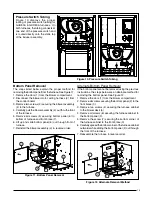
follow steps 1 - 12. See Figure 20 (page 35) for component 

location.
1. Shut off gas supply to the furnace at the meter or at a 

manual valve in the supply piping.

2. Turn off all power to the furnace and set the thermostat 

to its lowest setting.

3. Remove the burner door from the furnace.
4. Turn the gas control switch to the OFF position.
5. Disconnect the wires from the gas valve, igniter, flame 

sensor, and flame rollout switch.

Содержание 80+ AFUE

Страница 1: ...pplier s instructions If you cannot reach your gas supplier call the fire department RISQUE D INCENDIE OU D EXPLOSION Le non respect des avertissements de sécurité pourrait entraîner des blessures graves la mort ou des dommages matériels L installation et l entretien doivent être effectués par un installateur qualifié un organisme de service ou le fournisseur de gazstaller service agency or the ga...

Страница 2: ...emoval 15 Alternate Bottom Panel Removal 15 GAS SUPPLY PIPING 16 Leak Check 16 High Altitude Application 17 Conversion to LP Propane 19 ELECTRICAL WIRING 19 Line Voltage Wiring 19 Grounding 20 Thermostat Low Voltage Connections 21 Heat Anticipator 21 Twinning 21 START UP ADJUSTMENTS 22 Pre Start Checklist 22 Start Up Procedures 22 Verifying Adjusting Input Rate 22 Verifying Adjusting Temperature R...

Страница 3: ...on when handling this appliance or removing components Personalinjurycanoccurfromsharpmetal edgespresentinallsheetmetalconstructedequipment Do not store any of the following on or in contact with the unit Rags brooms vacuum cleaners or other cleaning tools spray or aerosol cans soap powders bleaches waxes cleaning compounds plastics or plastic containers paper bags or other paper products gasoline...

Страница 4: ...nces Duct Systems USandCANADA AirConditioningContractorsAssociation ACCA Manual D Sheet Metal and Air Conditioning ContractorsNationalAssociation SMACNA orAmerican Society of Heating Refrigeration and Air Conditioning Engineers ASHRAE Fundamentals Handbook Electrical Connections US National Electrical Code NEC ANSI NFPA 70 CANADA Canadian Electrical Code CSA C22 1 Gas Piping Gas Pipe Pressure Test...

Страница 5: ...s gas furnace may be used during construction if it is not in violation of any applicable codes and the following criteria are met The installation must meet all applicable codes The furnace must be permanently installed according to the instructions with the furnace including electrical supply gas supply duct work and venting The furnace must be controlled by a thermostat properly installed accor...

Страница 6: ...cordés à la systéme d évacuation évacuent correctementtelqueprescritci dessus rouvrirles portes et les fenêtres et remettre les ventilateurs d évacuation les registres de foyers et tout autre appareil fonctionnant au gaz à leur état de fonctionnement initial Carbon monoxide poisoning hazard Failure to follow the steps outlined below for each appliance connected to the venting system being placed i...

Страница 7: ...o the furnace The required sizing of these openings is determined by whetherinsideoroutsideairisusedtosupportcombustion the method by which the air is brought to the space and by the total input rate of all appliances in the space In all cases the minimum dimension of any combustion air opening is 3 inches Air From Inside If combustion air is taken from the heated space the two openings must each ...

Страница 8: ...Vertical Ducts Inlet Air Duct must be at least 1 sq in per 4 000 Btuh of total input rating Inlet and Outlet Ducts must extend above attic insulation Outlet Air Duct must be at least 1 sq in per 4 000 Btuh of total input rating Ventilation Louvers at each end of attic Attic Insulation 12 Max Furnace Water Heater Vent or Chimney Total Input Rating Btuh Minimum Free Area Each Opening Round Duct Diam...

Страница 9: ...ent sizing tables in the NFGC the MAX capacity of the vent must be greater than the furnaces high fire rate The MIN capacity must be lower than the low fire rate If the venting system is inappropriate for the furnace the venting system will need to be modified to comply with NFGC or local Installation In An Unconfined Space An unconfined space is an area including all rooms not separated by doors ...

Страница 10: ...ensate leakage or spillage The existing vent system should also be checked to make sure it remains in compliance with NFGC If it isn t the vent system must be brought into compliance before installing the furnace Horizontal Venting Horizontal vent systems must be sealed with a high temperaturesealantthatcanwithstandtemperaturesof 450 F Recommended sealants Dow Corning Sealant 736 RTV GE 106 RTV Hi...

Страница 11: ...gned so that the return air supply to the furnace is equal to the return air supply under normal indoor return air applications When a cooling system is installed which uses the furnace blower to provide airflow over the indoor coil the coil must be installed downstream on the outlet side of the furnace or in parallel with the furnace If a cooling system is installed in parallel with the furnace a...

Страница 12: ...to install all the needed gaskets and grommets around penetrations into the furnace such as for electrical wiring Furnace INstallATION These Installation procedures are suggested for typical furnace installations Since each installation is different the sequence of instructions may differ from the actual installation Only qualified HVAC technicians should install this furnace The installer must be...

Страница 13: ...gas furnaces are shipped with the bottom panel installed as shown in Figure 18 page 26 If the furnace is installed with side return air the bottom panel mustnotberemoved Ifthefurnaceisinstalledwithbottom return air the bottom panel must be removed See Bottom Panel Removal on page 15 Horizontal Furnaces WARNING The furnace must not be installed directly on carpeting tile oranycombustiblematerialoth...

Страница 14: ...amageorpersonalinjury WARNING Thedownflowsub basekitmustnotbeinstalled directly on carpeting tile or any combustible material other than wood flooring Failure to comply may result in fire property damage or personal injury Downflow sub base kits are factory supplied accessories andarelistedaccordingtothecabinetletterofthefurnace For A size cabinets use Sub Base kit 902974 only For B C and D size c...

Страница 15: ...e furnace in reverse order Bottom Panel Removal The steps listed below explain the proper method for removingthebottompanelfromthefurnace SeeFigure11 1 Remove the door 1 from the blower compartment 2 Disconnect the blower motor wiring harness 2 from the control board 3 Remove two screws 3 securing the blower assembly 4 to the furnace 4 Carefully pull the blower assembly 4 out thru the front of the...

Страница 16: ... OR EXPLOSION HAZARD Failure to follow safety warnings exactly could result in serious injury or property damage Installation and service must be performed by a qualified installer service agency or the gas supplier Do not store or use gasoline or other flammable vapors and liquids in the vicinity of this or any other appliance WHAT TO DO IF YOU SMELL GAS Do not try to light any appliance Do not t...

Страница 17: ...altitude For example at 2 000 feet the input needs to be reduced 8 at 3 000 feet 12 etc This deration is in reference to the input rate and gas heating value at sea level Toderatethefurnacerequiresknowingtheheatingvalueof the gas at the installation site Heating values at particular job sites vary for two reasons 1 The chemical mixture of the gas varies across regions and is expressed as the sea l...

Страница 18: ...STATUS FLAME 180 COOL HEAT 120 90 60 BLOWER OFF DELAY LOW ML MH HIGH EAC L1 XFMR HUM 24V L1A 5 NEUTRALS 2 6 3 4 1 7 8 9 5 2 6 3 4 1 FAN 8 3 5 See Note R C Y G W STATUS FLAME 180 COOL HEAT 120 90 60 BLOWER OFF DELAY LOW ML MH HIGH EAC L1 XFMR HUM 24V L1A 5 NEUTRALS 2 6 3 4 1 7 8 9 5 2 6 3 4 1 FAN R C Y G W STATUS FLAME 180 COOL HEAT 120 90 60 BLOWER OFF DELAY LOW ML MH HIGH EAC L1 XFMR HUM 24V L1A ...

Страница 19: ...ice size is 57 Whenconversioniscomplete verifythemanifoldpressure andinputratearecorrectaslistedintheTables Approved conversion kits are listed below The United States LP Propane Gas Sea Level and High Altitude Conversion Kit P N 904914 is for LP Propane conversion in the United States at altitudes between zero and 10 000 ft above sea level Please follow the instructions provided with the kit The ...

Страница 20: ...H80A GDD80A Furnace Input Btuh Cabinet Width in Nominal Electrical Supply Maximum Operating Voltage Minimum Operating Voltage Maximum Furnace Amperes Minimum Wire Gauge Maximum Fuse or Circuit Breaker Amps 045A3XE 45 000 14 1 4 115 60 1 127 103 6 3 14 15 054A3XE 54 000 14 1 4 115 60 1 127 103 6 3 14 15 072B4XE 72 000 17 1 2 115 60 1 127 103 9 7 14 20 072C5XE 72 000 21 115 60 1 127 103 9 0 14 15 09...

Страница 21: ...ally installed Please contact your distributor for the proper upgrade motor kit Heat Anticipator Set the heat anticipator according to the instructions supplied by the thermostat manufacturer To determine the heat anticipator setting 1 Add the current draw of the system components or 2 Measure the current flow on the thermostat R W circuit after the circulating blower motor has started Twinning Si...

Страница 22: ...steps until all of the checks in the previous steps have been completed 1 Set the thermostat to the lowest setting 2 Turn off all electrical power to the furnace 3 Follow the Operating Instructions on the label attached to the furnace 4 Set the thermostat above room temperature and verify the Operating Sequence Page 23 5 After 5 minutes of operation set the thermostat below roomtemperatureandverif...

Страница 23: ...in place of or upstream of the filter s 3 Setthethermostataboveroomtemperatureandobserve the Operating Sequence 4 Remove the close off immediately after the limit switch opens If the furnace continues to operate with no return air set the thermostat below room temperature shut off power to the furnace and replace the limit switch OPERATING SEQUENCE The operating sequences for the heating cooling a...

Страница 24: ...l the doors on the furnace after servicing or cleaning changing the filters Do not operate the furnace without all doors and covers in place Verify the thermostat is properly installed and is not being affected by drafts or heat from lamps or other appliances To achieve the best performance and minimize equipment failure it is recommended that a yearly maintenance checkup be performed At a minimum...

Страница 25: ...ly remove the inducer assembly from the furnace GDD80A models Carefully remove the inducer assembly and combustion tube assembly from the furnace DO NOT BREAK THE SEALS AT EACH END OF THE COMBUSTION AIR TUBE 14 Remove all screws securing the collector pan to the furnace 15 Removethecollectorpanandgasketfromthefurnace 16 Attach a round wire brush to a length of high grade stainlesssteelcable Attach...

Страница 26: ... 054A3XE 072B4XE 17 1 2 11 3 4 15 7 8 16 1 8 072C5XE 090B4XE 21 14 19 3 8 19 7 8 090C5XE 108C5XE 126D5XE 24 1 2 15 1 4 22 7 8 23 1 8 NOTE Dimensions shown in Inches 18 5 8 C 7 34 1 2 22 1 2 28 25 3 8 22 1 2 25 22 1 4 29 1 2 23 B 7 Gas 1 5 8 X 3 1 2 X 45 T stat Ø 7 8 Gas 1 5 8 X 3 1 2 Electric Ø 7 8 Front Brace D BOTTOM VIEW RIGHT SIDE LEFT SIDE TOP VIEW 19 A FRONT VIEW FLANGES Accepts 4 Type B Ven...

Страница 27: ...1 685 32 1 645 32 1 590 34 1 550 34 1 485 36 1 415 38 Med High 1 400 38 1 360 39 1 340 40 1 310 41 1 275 42 1 245 43 1 190 45 1 125 47 Med Low 1 235 43 1 215 44 1 180 45 1 155 46 1 130 47 1 100 48 1 060 50 1 005 53 Low 975 55 940 57 930 57 890 60 865 62 840 63 810 66 775 69 090B4XE Bottom Return 90 000 High 1 610 41 1 575 42 1 530 44 1 485 45 1 440 46 1 385 48 1 340 50 1 275 52 Med High 1 295 51 1...

Страница 28: ...270 63 1 225 65 1 175 68 108C5XE Side Return 108 000 High 2 295 35 2 235 36 2 180 37 2 110 38 2 050 39 1 975 41 1 900 42 1 810 44 Med High 2 130 38 2 075 39 2 035 39 1 970 41 1 915 42 1 845 43 1 765 45 1 675 48 Med Low 1 770 45 1 750 46 1 710 47 1 675 48 1 630 49 1 585 50 1 520 53 1 430 56 Low 1 445 55 1 425 56 1 410 57 1 375 58 1 350 59 1 320 61 1 275 63 1 225 65 108C5XE Side Bottom or 2 Sides 10...

Страница 29: ...260 53 1250 53 1220 55 1195 57 1170 57 1120 60 Med Low 1 155 58 1235 54 1115 60 1095 61 1065 63 1040 66 1015 66 980 68 Low 910 73 885 75 860 78 835 80 810 82 785 85 765 87 735 91 108C5XE 108 000 High 2 395 33 2 335 34 2 285 35 2 230 36 2 200 36 2 140 37 2 080 38 2 000 40 Med High 2 190 37 2 135 37 2 115 38 2 080 38 2 030 39 1 975 41 1 915 42 1 810 44 Med Low 1 785 45 1 770 45 1 740 46 1 725 46 1 6...

Страница 30: ...ff Diagnostic Description Low Flame Sensor Signal Flame Present FAULT CONDITIONS Yellow LED Continuous Flash On Alternating Flash Replaces 710915B IGNITOR INDUCER FLAME SENSOR C BLOWER LIMIT DOOR SWITCH R 4 SPEED MOTOR WHITE RED BLUE ORANGE BLACK GAS VALVE H MH ML L C FLAME ROLLOUT SUPPLY AIR LIMIT VENT LIMIT SWITCH ON SELECT MODELS R C Y G W LOW ML MH HIGH EAC L1 XFMR HUM 1 2 3 4 5 6 7 8 9 1 2 3 ...

Страница 31: ...PER REVOLUTION OF GAS METER 1 5 10 10 360 1 800 3 600 12 300 1 500 3 000 14 257 1 286 2 571 16 225 1 125 2 250 18 200 1 000 2 000 20 180 900 1 800 22 164 818 1 636 24 150 750 1 500 26 138 692 1 385 28 129 643 1 286 30 120 600 1 200 32 113 563 1 125 34 106 529 1 059 36 100 500 1 000 38 95 474 947 40 90 450 900 42 86 429 857 44 82 409 818 46 78 391 783 48 75 375 750 50 72 360 720 52 69 346 692 54 67...

Страница 32: ...7 57 57 ORIFICE SIZE 9 0 9 0 9 0 9 0 9 0 9 0 MANIFOLD PRESSURE 8 000 to 10 000 FT 59 57 57 57 57 57 ORIFICE SIZE 8 5 8 5 8 5 8 5 8 5 8 5 MANIFOLD PRESSURE LOCAL HEATING VALUES FOR NATURAL GAS ALTITUDE ABOVE SEA LEVEL BTU PER CUBIC FOOT 650 700 750 800 850 900 950 1 000 1 050 2 000 FT LOW LOW LOW LOW LOW LOW HIGH HIGH HIGH 3 000 FT LOW LOW LOW LOW LOW LOW HIGH HIGH HIGH 4 000 FT LOW LOW LOW LOW LOW...

Страница 33: ...LD PRESSURE 9 000 to 9 999 FT 51 49 49 49 49 49 ORIFICE SIZE 2 6 2 8 2 8 2 8 2 8 2 8 MANIFOLD PRESSURE Table 10 High Altitude Deration Chart for Natural Gas Low Heating Value NATURAL GAS w LOW HEATING VALUE ALTITUDE ABOVE SEA LEVEL INPUT BTU 45 000 54 000 72 000 90 000 108 000 126 000 0 to 1 999 FT 49 47 47 47 47 47 ORIFICE SIZE 3 5 3 5 3 5 3 5 3 5 3 5 MANIFOLD PRESSURE 2 000 to 2 999 FT 49 47 47 ...

Страница 34: ...t operate check the flame roll out switch and reset if necessary See Figure 20 for component location If the furnace operates when the flame rollout switch is reset contact a qualified service technician to identify and repair the problem Furnace COMPONENTS The descriptions below are various functional components that affect the operation and shutting down of this furnace Some of these components ...

Страница 35: ...Transformer Blower Assembly Control Board Main Air Limit Switch Figure 20 Component Locations Combustion Tube Gas Manifold Gas Valve Inducer Assembly Control Board Pressure Switch Transformer Blower Assembly behind blower panel Burner Assembly Flame Sensor Roll Out Switch Igniter Main Air Limit Switch Blower Door Switch behind blower panel Downflow Furnace ...

Страница 36: ...fully before starting the installation Return these instructions to the customer s package for future reference PROPOSITION 65 WARNING This product contains chemicals known to the state of California to cause cancer birth defects or other reproductive harm WARNING ELECTRICAL SYSTEM Electrical connections tight YES NO Line voltage polarity correct YES NO Supply Voltage _____________________________...

Отзывы: